🌟 Featured on Adafruit Blog!
We’re excited to share that this guide has been featured on the official Adafruit Blog, one of the most influential platforms in the maker and electronics community worldwide.
Here’s how they mentioned us:
Yes, they misspelled our name… but the link is spot on! 😄
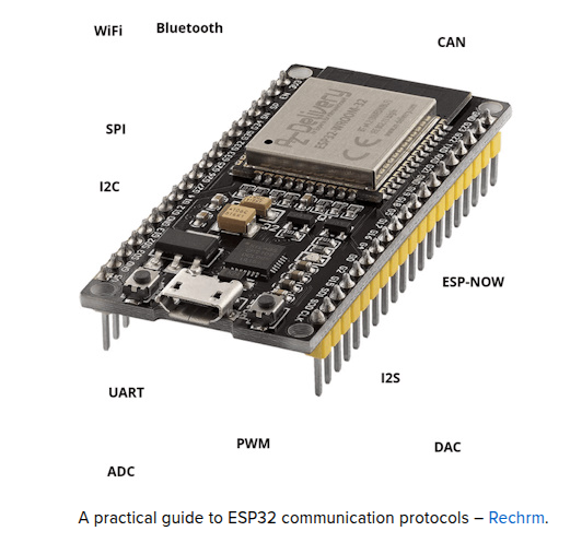
“A practical guide to ESP32 communication protocols – Rechrm.”
Despite the typo (it’s actually TechRm), we’re honored to be recognized for our work on ESP32 communication protocols.
Check out their feature here, and explore how our content is making an impact in the global tech scene! 🚀
Introduction
ESP32 and communication protocols. The ESP32 is a versatile and powerful microcontroller that has revolutionized the world of the Internet of Things (IoT) thanks to its advanced communication capabilities and its wide range of integrated features. One of the features that makes the ESP32 so popular among hobbyists, makers, and electronics engineers is its ability to support numerous communications protocols. These protocols allow the ESP32 to interface with a variety of devices and sensors, making it an ideal choice for a wide range of projects, from simple monitoring systems to complex automation systems.
The goal of this article is to provide a complete and detailed guide on the communication protocols supported by the ESP32. While there are many online resources that cover some of these protocols individually, it is rare to find a single resource that covers them all comprehensively. With this article, we aim to fill this gap, offering a comprehensive overview that can serve both beginners and experts.
What we will explain
In this article, we will explore the main communication protocols supported by the ESP32, including:
- Wi-Fi: the most common wireless communication protocol, used to connect devices to local networks and the internet.
- Bluetooth: including BR/EDR and BLE versions, for short-range communication with other Bluetooth devices.
- ESP-NOW: a wireless protocol developed by Espressif that allows direct communication between ESP32 devices without the need for a Wi-Fi network.
- UART: a serial protocol for communication between microcontrollers and other serial devices.
- SPI: a high-speed synchronous communications protocol used primarily to communicate with sensors and memory devices.
- I2C: a serial communications protocol used to connect low-speed devices such as sensors and displays.
- I2S: used for transmitting digital audio data.
- CAN: used in automotive and industrial applications for communication between microcontrollers.
- PWM: for precise control of devices such as motors and LEDs.
- ADC e DAC: for the conversion between analog and digital signals, essential for interfacing with sensors and actuators.
Why is it necessary to know these communication protocols?
Understanding the various communication protocols supported by the ESP32 is essential to fully exploit the potential of this microcontroller. Here because:
- Versatility in projects: each protocol has its specific advantages and ideal use cases. Knowing which protocol to use can make the difference between a working project and an inefficient one.
- Resource optimization: using the right protocol can optimize the use of microcontroller resources, improving energy efficiency and communication speed.
- Interoperability: many projects require interfacing with various devices and sensors. Knowing the protocols supported by ESP32 allows you to design interoperable and scalable systems.
- Reliability and safety: some protocols offer built-in security features that are crucial for sensitive applications. For example, Wi-Fi and Bluetooth support advanced security protocols to protect transmitted data.
- Professional development: for professional electronics engineers and developers, having a thorough understanding of communication protocols is essential for designing complex and reliable systems.
This article aims to be a complete and practical guide for all those who wish to understand and use the various communication protocols of the ESP32. Whether you are a beginner taking your first steps in electronics or an expert engineer looking to optimize your projects, you will find in these pages the information and resources necessary to make the most of the potential of the ESP32.

Wi-Fi
Description of the protocol
Wi-Fi (Wireless Fidelity) is a wireless communication technology that allows devices to connect to a local network or the Internet without the use of physical cables. It uses radio frequencies to transmit data between devices and an access point (router). The ESP32 supports the 802.11 b/g/n Wi-Fi standards, operating primarily in the 2.4 GHz frequency bands. This capability allows the ESP32 to connect to existing Wi-Fi networks, create its own Wi-Fi networks, or communicate directly with other devices via Wi-Fi Direct.
The ESP32 supports the following Wi-Fi standards:
- 802.11b: the first Wi-Fi standard, with a theoretical maximum speed of 11 Mbps, operating in the 2.4 GHz band.
- 802.11g: successor to 802.11b, with a theoretical maximum speed of 54 Mbps, also operating in the 2.4 GHz band.
- 802.11n: improvement on previous standards, with theoretical speeds of up to 600 Mbps using MIMO (Multiple Input Multiple Output) technology. 802.11n operates in the 2.4GHz and 5GHz bands, but the ESP32 is limited to the 2.4GHz band.
Wi-Fi operation mode
The ESP32 can operate in different Wi-Fi modes:
- Station Mode (STA):
- in this mode, the ESP32 acts like a client device that connects to a Wi-Fi access point (AP), such as a router. Once connected, it can communicate with other devices on the same network and access the Internet. This is the most common mode for IoT devices that need to send data to a server or receive over-the-air (OTA) updates.
- Access Point Mode (AP):
- in AP mode, the ESP32 acts as an access point, creating its own Wi-Fi network that other devices can connect to. This is useful for applications that require a local network without an external router, such as configuring a device or communicating between devices.
- Station + Access Point Mode (STA + AP):
- the ESP32 can function simultaneously as a client and access point, allowing communication with a Wi-Fi router and at the same time providing a local network for other devices. This mode is useful for applications that require communicating with an external network and creating a local network for control or configuration.
- Wi-Fi Direct:
- this mode allows direct communication between Wi-Fi devices without the need for an intermediate access point. It is useful for applications that require fast, short-range data transfers between devices.
Wi-Fi security
Security is a crucial aspect of Wi-Fi communications. The ESP32 supports various security protocols to protect transmitted data:
- WEP (Wired Equivalent Privacy): an outdated security protocol with known vulnerabilities. It is not recommended for use in new applications.
- WPA (Wi-Fi Protected Access): improves security over WEP, but also has known vulnerabilities.
- WPA2: currently the most common Wi-Fi security standard, using AES (Advanced Encryption Standard) to encrypt data. WPA2 is widely considered secure and reliable.
- WPA3: the latest Wi-Fi security standard, offering improved protection against brute-force attacks and other vulnerabilities.
Frequencies and channels
Wi-Fi operates primarily in the 2.4GHz band, which is split into channels. Each channel is 20 MHz wide, but there are also options for 40 MHz channels to increase data transfer speed. However, using wider channels may cause interference with other Wi-Fi devices operating in the same band.
MIMO technology
MIMO (Multiple Input Multiple Output) technology is used in the 802.11n standard to improve data transfer capacity and speed. It uses multiple antennas to transmit and receive multiple data streams simultaneously, significantly improving Wi-Fi performance.
Common applications
- Connection to local networks and the Internet:
- Smart Home: the ESP32 can be used to control smart home devices, such as lights, thermostats, and locks, via a Wi-Fi connection.
- IoT (Internet of Things): allows you to monitor and control remote sensors and actuators via an Internet connection.
- Streaming and data transfer: applications that require the transfer of large amounts of data, such as audio/video streaming and over-the-air (OTA) firmware updates.
- Creating Wi-Fi networks:
- Access point: the ESP32 can act as an access point (AP), allowing other devices to connect to it.
- Wi-Fi direct: direct peer-to-peer communication between devices without the need for an intermediate access point.
Implementation with ESP32
Implementing Wi-Fi with the ESP32 is simple thanks to the WiFi.h library included in the Arduino development environment. Here is a code example that shows how to connect to a Wi-Fi network:
#include <WiFi.h>

const char* ssid = "your_SSID";
const char* password = "your_PASSWORD";

void setup() {
  Serial.begin(115200);
  WiFi.begin(ssid, password);

  while (WiFi.status() != WL_CONNECTED) {
    delay(1000);
    Serial.println("Connecting to WiFi...");
  }

  Serial.println("Connected to WiFi");
  Serial.print("IP Address: ");
  Serial.println(WiFi.localIP());
}

void loop() {
  // Code to use the Wi-Fi connection
}
This simple example configures the ESP32 to connect to a Wi-Fi network using the specified credentials. Once connected, the IP address assigned to the device is printed on the Serial Monitor.
Advantages and disadvantages
- Advantages:
- Wide compatibility: compatible with most home and commercial Wi-Fi networks.
- High data transfer speed: ideal for applications requiring fast and reliable data transfer.
- Long range: Wi-Fi coverage can extend to several tens of meters, depending on the environment and the hardware used.
- Disadvantages:
- High energy consumption: the ESP32’s Wi-Fi module consumes a significant amount of power, making it less suitable for long-lasting battery applications.
- Possible interference: operating in the 2.4 GHz band, Wi-Fi can suffer interference from other devices that use the same band, such as microwaves and cordless phones.
- Safety: Wi-Fi networks can be vulnerable to attacks, so it is essential to implement appropriate security measures, such as the use of WPA2.
Additional resources
- Espressif Wi-Fi Documentation: Espressif official documentation for using Wi-Fi with the ESP32.
- WiFi Library for Arduino: documentation of the WiFi library for Arduino, which can also be used with the ESP32.
Wi-Fi is one of the most powerful and versatile communication protocols supported by the ESP32. Its ability to connect devices to local networks and the Internet, combined with ease of deployment and broad compatibility, makes it an ideal choice for a wide range of IoT and smart home applications. With a thorough understanding of how Wi-Fi works and its advantages and disadvantages, highly effective and reliable projects can be designed and implemented with the ESP32.
Bluetooth
Description of the protocol
Bluetooth is a short-range wireless communication technology that allows data to be exchanged between electronic devices. Using radio frequencies in the 2.4 GHz ISM band, Bluetooth is designed to be simple to set up and use, offering robust and reliable connections for a variety of applications, from wearable devices to audio systems and sensor networks.
The ESP32 supports two main versions of Bluetooth: Bluetooth Classic (BR/EDR) and Bluetooth Low Energy (BLE). Each version has its own unique features and specific applications.
Bluetooth Classic (BR/EDR)
Bluetooth Classic, also known as BR/EDR (Basic Rate/Enhanced Data Rate), is designed for high-speed data transmission over short distances. Its main features include:
- Transfer speed: up to 3 Mbps using EDR.
- Service Profiles: wide range of standardized profiles for different applications, such as audio (A2DP), file transfer (FTP) and personal networks (PAN).
- Continuous connection: ideal for applications that require a continuous and reliable connection, such as wireless headphones and audio devices.
Bluetooth Low Energy (BLE)
Bluetooth Low Energy, often abbreviated to BLE, is designed for applications requiring low power consumption and intermittent data transmissions. BLE is particularly suitable for IoT devices, sensors and wearables. Its main features include:
- Energy consumption: much lower than Bluetooth Classic, making it ideal for battery-powered devices.
- Transfer Speed: typically up to 1 Mbps, sufficient for most IoT applications.
- Communication methods: publishing and subscription via advertising packets, one-to-one connections and broadcasting.
How Bluetooth operates on the ESP32
- Bluetooth Classic mode:
- Client (Slave): the ESP32 can act as a client device, connected to a Bluetooth host such as a phone or computer.
- Host (Master): the ESP32 can act as a host device, managing the connection and communication with client devices.
- Bluetooth Low Energy (BLE) mode:
- Central: the ESP32 works as a central device, scanning and connecting to peripheral devices.
- Peripheral: the ESP32 acts as a peripheral device, advertising its presence and waiting for connection from a central device.
- Observer: the ESP32 can operate in observer mode, monitoring BLE advertising packets without establishing connections.
- Broadcaster: the ESP32 can transmit advertising packets to multiple devices without establishing a direct connection.
Bluetooth security
Security is fundamental to ensure the protection of data transmitted via Bluetooth. Security measures include:
- Pairing: authentication process between two Bluetooth devices to establish a secure connection.
- Cryptography: protects data transmitted between paired devices using encryption keys.
- Authentication: verifies the identity of devices to prevent unauthorized access.
Common applications
Bluetooth is widely used in several applications:
- Audio and multimedia:
- Wireless headphones and earphones: high-quality connection for stereo audio.
- Portable speakers: audio streaming from smartphone or computer.
- Wearable devices and health:
- Fitness trackers and smartwatches: synchronization of physical activity and health data.
- Medical sensors: health monitoring and sending data to mobile devices.
- Home automation and automation:
- Controlling smart home devices: management of lights, thermostats and smart locks.
- Sensor networks: environmental monitoring and home automation.
- Data transfer and synchronization:
- File exchange: transfer files between devices without internet connection.
- Data synchronization: synchronization of contacts, calendars and messages.
Implementation with ESP32
Here is an example code to implement a Bluetooth Classic connection with the ESP32:
#include <BluetoothSerial.h>

BluetoothSerial SerialBT;

void setup() {
  Serial.begin(115200);
  SerialBT.begin("ESP32Test"); // Bluetooth device name
  Serial.println("Bluetooth Started! Ready to pair.");
}

void loop() {
  if (SerialBT.available()) {
    char incomingChar = SerialBT.read();
    Serial.print(incomingChar);
  }
}
For BLE, here is an example code for a peripheral device:
#include <BLEDevice.h>
#include <BLEUtils.h>
#include <BLEServer.h>

BLEServer* pServer = NULL;
BLEService* pService = NULL;
BLECharacteristic* pCharacteristic = NULL;

void setup() {
  Serial.begin(115200);
  BLEDevice::init("ESP32_BLE"); // Bluetooth device name
  pServer = BLEDevice::createServer();
  pService = pServer->createService(BLEUUID(SERVICE_UUID));
  pCharacteristic = pService->createCharacteristic(
                      BLEUUID(CHARACTERISTIC_UUID),
                      BLECharacteristic::PROPERTY_READ |
                      BLECharacteristic::PROPERTY_WRITE
                    );
  pService->start();
  BLEAdvertising *pAdvertising = BLEDevice::getAdvertising();
  pAdvertising->addServiceUUID(BLEUUID(SERVICE_UUID));
  pAdvertising->start();
}

void loop() {
  //  BLE code
}
Advantages and disadvantages
- Advantages:
- Low Power Consumption (BLE): ideal for battery-operated devices.
- Ease of integration: wide support for various devices and platforms.
- Various operating modes: suitable for a wide range of applications.
- Disadvantages:
- Limited range: generally up to 10 meters for Bluetooth Classic, up to 100 meters for BLE in ideal conditions.
- Slower transfer speed: than Wi-Fi.
- Possible interference: in the 2.4 GHz band, similar to Wi-Fi.
Additional resources
- Espressif Bluetooth Documentation: official Espressif documentation for using Bluetooth with the ESP32.
- BluetoothSerial Library for Arduino: library for implementing Bluetooth Classic.
- ESP32 BLE Arduino Library: library for implementing BLE with ESP32.
Bluetooth, with its Classic and Low Energy variants, offers a versatile and reliable means for short-range wireless communication. The ESP32’s ability to support both versions makes this microcontroller ideal for a wide range of applications, from wearable devices to sensor networks and audio systems. With a thorough understanding of how Bluetooth works and its modes of operation, you can design and implement innovative and efficient projects with the ESP32.
ESP-NOW
Description of the protocol
ESP-NOW is a wireless communication protocol developed by Espressif Systems for the ESP8266 and ESP32 microcontrollers. This protocol is designed for low-latency data transmission between devices, without the need for a traditional Wi-Fi connection or access point (AP). ESP-NOW uses a peer-to-peer communication mode that allows devices to communicate directly with each other, making it ideal for sensor networks, automation applications and other situations where fast and efficient communication is needed.
Main features
- Low latency:
- ESP-NOW is designed to offer low-latency communications, making it suitable for real-time applications such as remote control and data collection from distributed sensors.
- Peer-to-Peer communication:
- ESP32 devices can communicate directly with each other without the need for a Wi-Fi router. This reduces network complexity and hardware requirements.
- Energy efficiency:
- thanks to its low latency and lack of overhead associated with managing a full Wi-Fi connection, ESP-NOW is also very energy efficient, making it ideal for battery-powered devices.
- Broadcast capability:
- ESP-NOW supports transmitting data to multiple devices simultaneously. A single device can send data to multiple peers in a single transmission packet, improving the efficiency of communication in sensor networks.
- Safety:
- ESP-NOW supports encryption to ensure that transmitted data is protected from unauthorized access. Each peer can be configured with a unique encryption key for secure communications.
Communication methods
- Unicast:
- direct communication between two devices. A device sends a specific message to another recipient device.
- Multicast:
- a device sends a message to a group of devices. This is useful for simultaneous updates or for syncing data between multiple devices.
- Broadcast:
- one device sends a message to all ESP-NOW devices within range. This is useful for announcements or for sending general commands to a network of devices.
Common applications
ESP-NOW is well suited for a number of applications, including:
- Wireless sensor networks:
- used to create sensor networks that collect and transmit environmental data such as temperature, humidity, and pressure. These sensors can communicate directly with each other and with a central node for monitoring and data collection.
- Home automation:
- implemented in home control systems to manage lights, locks, thermostats, and other devices without the need for a Wi-Fi router. This improves responsiveness and reduces network complexity.
- Remote control:
- used in remote control applications where rapid response is required, such as in the case of drones, robots and remotely operated vehicles.
- Data transfer between devices:
- ESP-NOW can be used to transfer data quickly between devices
Operating modes
ESP-NOW works on a connectionless transmit and receive mechanism. This means that devices do not have to establish a connection before starting communication. This significantly reduces the time needed to initiate data transmission.
- Sending data:
- an ESP32 device can send data packets directly to one or more specific devices using their MAC addresses. There is no need to go through a router or centralized network, which reduces latency.
- Receiving data:
- ESP32 devices can be configured to receive packets from one or more ESP devices. They can operate in continuous listening mode or be programmed to wake up periodically and receive data, further reducing power consumption.
Implementation with ESP32
Here is an example code to implement ESP-NOW on ESP32:
#include <esp_now.h>
#include <WiFi.h>

// MAC address of the peer to send data to
uint8_t broadcastAddress[] = {0x24, 0x0A, 0xC4, 0x11, 0x22, 0x33};

typedef struct struct_message {
    char a[32];
    int b;
    float c;
    bool d;
} struct_message;

// Creating the message to send
struct_message myData;

void setup() {
  Serial.begin(115200);

  // Set Wi-Fi to station mode
  WiFi.mode(WIFI_STA);

  // Initializes ESP-NOW
  if (esp_now_init() != ESP_OK) {
    Serial.println("Error initializing ESP-NOW");
    return;
  }

  // Registers the peer
  esp_now_peer_info_t peerInfo;
  memcpy(peerInfo.peer_addr, broadcastAddress, 6);
  peerInfo.channel = 0;
  peerInfo.encrypt = false;

  // Adds peer
  if (esp_now_add_peer(&peerInfo) != ESP_OK) {
    Serial.println("Failed to add peer");
    return;
  }
}

void loop() {
  // Configures the message to send
  strcpy(myData.a, "Hello ESP-NOW");
  myData.b = random(1,20);
  myData.c = 1.2;
  myData.d = false;

  // Sends the message
  esp_err_t result = esp_now_send(broadcastAddress, (uint8_t *) &myData, sizeof(myData));

  if (result == ESP_OK) {
    Serial.println("Sent with success");
  } else {
    Serial.println("Error sending the data");
  }

  delay(2000);
}
Advantages and disadvantages
- Advantages:
- Low latency: direct communication between ESP32 devices reduces latency compared to using a Wi-Fi network.
- Energy efficiency: ideal for battery powered applications due to low power consumption.
- Easy setup: it does not require complex network infrastructures such as routers or access points.
- Scalability: supports communication with multiple devices simultaneously, making it ideal for sensor networks.
- Disadvantages:
- Limited range: the communication distance is similar to that of Wi-Fi and may be affected by physical obstacles.
- Limited data transfer capacity: not suitable for transferring large amounts of data compared to protocols such as Wi-Fi.
- Limited support: the protocol is specific to ESP devices, limiting interoperability with other devices.
Additional resources
- Espressif ESP-NOW Documentation: Espressif official documentation for using ESP-NOW with the ESP32.
- ESP-NOW Examples on GitHub: examples of implementing ESP-NOW with the ESP-IDF.
ESP-NOW is a unique and powerful communication protocol developed by Espressif that offers an efficient, low-latency solution for communication between ESP32 devices. With its ability to operate without complex network infrastructure and its low power consumption, ESP-NOW is ideal for IoT applications, sensor networks and distributed control systems. Understanding the features and benefits of ESP-NOW allows you to make the most of the ESP32’s capabilities in your wireless communications projects.
UART
Description of the protocol
UART (Universal Asynchronous Receiver-Transmitter) is one of the most common and used serial communication protocols in electronics. This protocol allows the transmission of data between two devices via a serial communication line. It is widely used for its simplicity and reliability, making it ideal for a wide range of applications, from microcontrollers to computers.
Main features
- Asynchronous communication:
- unlike synchronous protocols, UART does not require a shared clock between the transmitting and receiving devices. Instead, each device uses its own internal clock to sample data, making communication more flexible and less prone to synchronization problems.
- Data frames:
- data is transmitted in “frames” that include a start bit, a configurable number of data bits (usually 8), an optional parity bit, and one or two stop bits. This structure helps ensure the integrity of the transmitted data.
- Transmission speed:
- data transmission speed (baud rate) can vary widely, typically from 9600 baud up to several megabits per second, depending on the capabilities of the hardware and the needs of the application.
- Bidirectional:
- UART is bidirectional, allowing simultaneous communication between two devices, with one line for transmission (TX) and one for reception (RX).
- Error checking:
- the protocol includes error checking mechanisms, such as the parity bit, to ensure that the data received is correct. However, reliability also depends on the quality of the connection and the appropriate baud rate configuration.
Operating modes
- Data transmission:
- the UART transmitter converts the data bytes into a serial stream of bits, adding the start bit, data bits, parity bit (if used), and stop bits. This data stream is sent on the TX line.
- Receiving data:
- the UART receiver monitors the RX line to detect the start bit. Once detected, it begins sampling data bits based on the configured baud rate, reconstructing the original byte and checking for errors with the parity bit.
Common applications
- Microcontrollers and sensors:
- UART is commonly used for communication between microcontrollers and sensor modules or other peripheral devices, such as GPS, GSM modules, and LCD displays.
- Debugging interfaces:
- many devices use UARTs for debug interfaces, allowing developers to monitor and control the system during development and troubleshooting.
- Communication between computers and external devices:
- UART is widely used for communication between computers and external devices via RS232 serial ports.
Implementation with ESP32
Here is an example of how to configure an ESP32 to use UART:
#include <HardwareSerial.h>

HardwareSerial MySerial(1);

void setup() {
  Serial.begin(115200);
  MySerial.begin(9600, SERIAL_8N1, 16, 17); // Configures UART: baud rate 9600, 8N1, TX pin 16, RX pin 17

  Serial.println("UART Test");
  MySerial.println("Hello, UART!");
}

void loop() {
  if (MySerial.available()) {
    char c = MySerial.read();
    Serial.print(c);
  }
  if (Serial.available()) {
    char c = Serial.read();
    MySerial.print(c);
  }
}
In this example, we configure the ESP32 to use hardware serial port 1 with a baud rate of 9600. Data received on MySerial is printed on the Serial Monitor and vice versa.
Advantages and disadvantages
- Advantages:
- Simplicity: UART is easy to implement and use, making it ideal for simple and direct serial communication.
- Versatility: widely supported and used in numerous devices, from microcontrollers to computers.
- Reliability: error control mechanisms such as the parity bit help ensure the integrity of the transmitted data.
- Bidirectionality: allows simultaneous communication between two devices through separate transmission and reception lines.
- Disadvantages:
- Distance limits: the maximum cable length for reliable UART communication is limited, typically to a few meters, depending on the transmission speed and quality of the cable.
- Limited speed: although it can reach high speeds, it is not suitable for transferring large amounts of data compared to protocols such as SPI or I2C.
- Point to Point Communication: UART is inherently point-to-point, meaning it doesn’t naturally support communication with multiple devices on a single line.
Additional resources
- Espressif UART Documentation: official Espressif documentation for using UART with the ESP32.
- Arduino UART Tutorial: documentation of the Serial library for Arduino, which can also be used with the ESP32.
UART is one of the most important and versatile serial communication protocols used in electronics. Its simplicity and reliability make it ideal for a wide range of applications, from embedded systems to consumer devices. With the ESP32, UART implementation is easy and straightforward, allowing you to make the most of the microcontroller’s communication capabilities for various projects. Knowing the operating details and advantages of UART is essential for designing efficient and reliable communication systems.
SPI
Description of the protocol
SPI (Serial Peripheral Interface) is a synchronous serial communication protocol used primarily for high-speed communication between a microcontroller and one or more peripheral devices. It was developed by Motorola in the 1980s and has established itself as one of the fastest and most reliable communications standards for embedded applications.
Main features
- Synchronous communication:
- unlike asynchronous protocols like UART, SPI uses a common clock to synchronize data transmission between the master and slave devices. The clock is generated by the master device.
- 4 wire configuration:
- SPI uses a four main wire configuration:
- MOSI (Master Out Slave In): line for transmitting data from the master to the slaves.
- MISO (Master In Slave Out): line for transmitting data from the slaves to the master.
- SCK (Serial Clock): clock line generated by the master to synchronize communication.
- SS/CS (Slave Select/Chip Select): line used by the master to select the slave device to communicate with.
- SPI uses a four main wire configuration:
- High transmission speed:
- SPI supports very high transmission speeds, typically up to several tens of megabits per second, making it ideal for applications that require rapid data transfer, such as displays, flash memories, and high-speed sensors.
- Full-Duplex communication:
- SPI supports full-duplex communication, allowing simultaneous data transmission between the master and slave.
- Flexibility in configuration:
- SPI protocol configuration is very flexible. The master can communicate with multiple slaves using separate SS lines for each. Additionally, data transfer modes (clock phase and polarity) can be configured to suit the requirements of various devices.
Operating modes
- Master and Slave:
- the master device generates the clock and controls the communication. Can select one or more slave devices across SS lines.
- slave devices respond to commands from the master. Only the selected slave device communicates with the master at any given time.
- Clock configuration:
- the SPI clock can be configured in four modes, determined by the combination of polarity (CPOL) and phase (CPHA):
- CPOL = 0, CPHA = 0: the clock is low at idle, data is sampled on the rising edge.
- CPOL = 0, CPHA = 1: the clock is low at rest, data is sampled on the falling edge.
- CPOL = 1, CPHA = 0: the clock is high at rest, data is sampled on the falling edge.
- CPOL = 1, CPHA = 1: the clock is high at idle, data is sampled on the rising edge.
- the SPI clock can be configured in four modes, determined by the combination of polarity (CPOL) and phase (CPHA):
Common applications
- Memories and storage:
- Flash memories: communication with flash memories for non-volatile data storage.
- SD Card: interfacing with SD cards to store large amounts of data.
- Display and user interfaces:
- LCD and OLED displays: fast data transfer for quick display updates.
- Touchscreen: communication with touchscreen controller for user input.
- Sensors and peripherals:
- Temperature and pressure sensors: reading data from high precision sensors.
- A/D and D/A converters: interfacing with analog-digital and digital-analog converters.
Implementation with ESP32
Here is an example of how to configure an ESP32 to communicate with an SPI device:
#include <SPI.h>

const int SS_PIN = 5;

void setup() {
  Serial.begin(115200);

  // Configures the SPI
  SPI.begin(); // SCK: 18, MISO: 19, MOSI: 23, SS: 5

  pinMode(SS_PIN, OUTPUT);
  digitalWrite(SS_PIN, HIGH);
}

void loop() {
  // Sends data via SPI
  digitalWrite(SS_PIN, LOW); // Selects the slave device
  SPI.transfer(0x42); // Sends a data byte
  digitalWrite(SS_PIN, HIGH); // Deselect the slave device

  delay(1000); // Waits a second before sending the next byte
}
In this example, the ESP32 is configured to communicate with an SPI slave device. The slave select (SS) pin is configured as an output and initially set high (not selected). In the main loop, the ESP32 selects the slave by setting the SS pin low, transfers one byte of data (0x42), and then deselects the slave by setting the SS pin high again. The process is repeated every second.
Advantages and disadvantages
- Advantages:
- High speed: SPI can operate at very high speeds, making it ideal for applications that require rapid data transfer.
- Flexibility: supports communication with multiple devices using separate SS lines.
- Simplicity: the protocol is relatively simple and does not require complex protocol overhead.
- Disadvantages:
- Number of pins: the 4-wire configuration can be a limitation in applications with a limited number of pins available.
- One-way communication: although it supports full-duplex, SPI is basically point-to-point and is not ideal for complex networks of devices.
- Lack of standardization for the superior protocol: unlike I2C, there is no common standardization for managing multiple devices on the same SPI line, leading to proprietary implementations.
Additional resources
- Espressif SPI Documentation: Espressif official documentation for using SPI with the ESP32.
- Arduino SPI Library: documentation of the SPI library for Arduino, also usable with the ESP32.
SPI is an extremely versatile and fast serial communication protocol, ideal for applications that require rapid data transfer. With the ESP32, configuring and using SPI is simple thanks to the available libraries and documentation. Understanding the features, benefits, and limitations of SPI allows you to design efficient, high-performance communications systems for a wide range of embedded applications.
I2C
Description of the protocol
I2C (Inter-Integrated Circuit) is a synchronous serial communication protocol developed by Philips Semiconductor (now NXP Semiconductors) in the 1980s. It is designed to enable communication between short-range devices within a printed circuit board (PCB). I2C is widely used to connect microcontrollers, sensors, displays and other peripheral modules in embedded systems.
Main features
- Synchronous communication:
- I2C uses a shared clock to synchronize data transmission between the master and slave devices. The clock is generated by the master, allowing synchronous communication between all connected devices.
- 2 wire configuration:
- I2C uses only two lines for communication:
- SDA (Serial Data Line): line for transmitting and receiving data.
- SCL (Serial Clock Line): line for the clock, generated by the master.
- I2C uses only two lines for communication:
- Addressing:
- each slave device connected to the I2C bus has a unique 7-bit or 10-bit address. The master uses this address to select the device to communicate with.
- Transmission speed:
- I2C supports different baud rates:
- Standard Mode: up to 100 kbps.
- Fast Mode:up to 400 kbps.
- Fast Mode Plus: up to 1 Mbps.
- High-Speed Mode: up to 3.4 Mbps.
- I2C supports different baud rates:
- Support for multiple Masters:
- the I2C protocol supports the presence of multiple masters on the same bus, although only one master can control the bus at a time.
- Arbitrage and error detection:
- I2C includes mechanisms for bus arbitration when multiple masters try to communicate simultaneously. In the event of conflicts, a master can relinquish control of the bus. Furthermore, the protocol includes error detection through acknowledgment bits.
Operating modes
- Master and Slave:
- the master controls the clock and starts communication by sending the address of the slave it wants to communicate with. Slaves respond when their address is recognized.
- Data transmission and reception:
- data is transmitted in 8-bit packets. Each byte of data transmitted must be followed by an acknowledgment (ACK) bit from the receiver.
- Start and Stop conditions:
- an I2C communication begins with a start condition (SDA goes from high to low while SCL is high) and ends with a stop condition (SDA goes from low to high while SCL is high).
Common applications
- Interfacing with sensors:
- Temperature and humidity sensors: reading data from environmental sensors for monitoring applications.
- Accelerometers and gyroscopes: interfacing with motion sensors for applications such as drones and wearable devices.
- Display and user interfaces:
- LCD and OLED displays: display control for viewing information.
- Keyboards: reading input from keyboards and buttons.
- Memories and storage devices:
- EEPROM: storage of non-volatile data.
- RTC (Real-Time Clocks): real time management in embedded applications.
Implementation with ESP32
Here is an example of how to configure an ESP32 to communicate with an I2C device:
#include <Wire.h>

const int I2C_ADDRESS = 0x3C; // I2C device address
const int SDA_PIN = 21;       // Pin SDA
const int SCL_PIN = 22;       // Pin SCL

void setup() {
  Serial.begin(115200);

  //Initialize I2C communication
  Wire.begin(SDA_PIN, SCL_PIN);

  // Send a command to the I2C device
  Wire.beginTransmission(I2C_ADDRESS);
  Wire.write(0x00);  // Send byte 0x00 to the selected I2C device
  Wire.endTransmission();

  // Request data from I2C device
  Wire.requestFrom(I2C_ADDRESS, 1);  // Request 1 byte of data
  while (Wire.available()) {
    char c = Wire.read();
    Serial.print(c);
  }
}

void loop() {
  // Code to periodically perform other operations
  delay(1000);
}
In this example, the ESP32 is configured to communicate with an I2C device with the address 0x3C. The SDA and SCL pins are configured on pins 21 and 22 respectively. In setup(), the ESP32 sends a command to the device and then requests a byte of data which is read and printed on the Serial Monitor.
Advantages and disadvantages
- Advantages:
- Efficient use of pins: it uses only two pins for communication, allowing you to connect multiple devices on the same bus.
- Support for multiple devices: up to 127 slave devices can be connected to a single master.
- Flexibility: supports various devices with different speeds and requirements on the same bus.
- Disadvantages:
- Slower speed: although it supports speeds up to 3.4 Mbps, it is slower than protocols like SPI.
- Implementation complexity: requires management of acknowledgment bits and start/stop conditions, which can increase the complexity of the code.
- Distance limitation: the length of the bus is limited due to parasitic capacitances and line resistance, making it less suitable for long-range communications.
Additional resources
- Espressif I2C Documentation: official Espressif documentation for using I2C with the ESP32.
- Arduino I2C (Wire) Library: documentation of the I2C library for Arduino, also usable with the ESP32.
I2C is an essential serial communication protocol for interfacing with various peripheral devices in embedded systems. Its simplicity and flexibility, along with the ability to connect multiple devices using just two lines, make it ideal for many applications. With the ESP32, the implementation of I2C is facilitated by the available libraries, allowing you to make the most of the microcontroller’s capabilities. In-depth knowledge of the characteristics, advantages and limitations of I2C allows you to design efficient and reliable communication systems, optimizing hardware resources and improving the overall performance of embedded designs.
I2S
Description of the protocol
I2S (Inter-IC Sound) is a synchronous serial communication protocol developed specifically for transmitting digital audio data between integrated circuits. It is designed to connect digital-to-analog converters (DACs), analog-to-digital converters (ADCs), and digital audio processors efficiently and with low latency, maintaining high audio signal quality.
Main features
- Synchronous communication:
- I2S uses a common clock to synchronize the transmission of audio data between devices. The master generates the clock and the slave devices follow it, ensuring precise and synchronized transmission of audio data.
- 3 Wire Configuration:
- I2S generally uses three main lines for communication:
- SD (Serial Data): line for audio data.
- SCK (Serial Clock): serial clock line, generated by the master.
- WS (Word Select): word selection line, which indicates which channel (left or right) is currently transmitting.
- I2S generally uses three main lines for communication:
- Support for multi-channel:
- I2S supports multi-channel audio data transmission, making it ideal for applications such as surround sound.
- High audio quality:
- the protocol is designed to transmit digital audio data with low latency and high fidelity, maintaining the integrity of the audio signal during transmission.
- Operating modes:
- Master and Slave: the master device controls the clock and word selection, while the slave devices transmit or receive data in sync with the master’s clock.
Common applications
- Digital-to-Analog Converters (DAC):
- used to send digital audio data to DACs, which convert them to analog audio signals for playback through speakers or headphones.
- Analog-Digital Converters (ADC):
- used to receive digital audio data from ADCs, which convert analog audio signals into digital data for further processing or recording.
- Digital audio processors:
- used to connect digital audio processors that process digital audio signals to improve sound quality or apply audio effects.
- Multi-channel audio systems:
- used in multi-channel audio systems such as home theater systems to transmit high-fidelity multi-channel audio.
Implementation with ESP32
Here is an example of how to configure an ESP32 to transmit audio data using I2S:
#include <driver/i2s.h>

const int I2S_WS = 25; // Word Select (LRC)
const int I2S_SCK = 26; // Serial Clock (BCK)
const int I2S_SD = 22;  // Serial Data (DIN)

void setup() {
  Serial.begin(115200);

  // I2S configuration
  i2s_config_t i2s_config = {
    .mode = I2S_MODE_MASTER | I2S_MODE_TX,
    .sample_rate = 44100,
    .bits_per_sample = I2S_BITS_PER_SAMPLE_16BIT,
    .channel_format = I2S_CHANNEL_FMT_RIGHT_LEFT,
    .communication_format = I2S_COMM_FORMAT_I2S,
    .intr_alloc_flags = ESP_INTR_FLAG_LEVEL1,
    .dma_buf_count = 8,
    .dma_buf_len = 64,
    .use_apll = false,
    .tx_desc_auto_clear = true,
    .fixed_mclk = 0
  };

  i2s_pin_config_t pin_config = {
    .bck_io_num = I2S_SCK,
    .ws_io_num = I2S_WS,
    .data_out_num = I2S_SD,
    .data_in_num = I2S_PIN_NO_CHANGE
  };

  // Installation and configuration of I2S pins
  i2s_driver_install(I2S_NUM_0, &i2s_config, 0, NULL);
  i2s_set_pin(I2S_NUM_0, &pin_config);
}

void loop() {
  // Simulated audio data (an array of audio samples)
  int16_t audio_data[64];
  for (int i = 0; i < 64; i++) {
    audio_data[i] = (i % 2 == 0) ? 32767 : -32768; // Simulated square waves
  }
  size_t bytes_written;
  i2s_write(I2S_NUM_0, audio_data, sizeof(audio_data), &bytes_written, portMAX_DELAY);
  delay(100); // Delay to demonstrate continuous use
}
In this example, the ESP32 is configured to transmit audio data using the I2S protocol. The WS, SCK, and SD pins are configured on pins 25, 26, and 22, respectively. In the loop function of this example, audio_data contains an array of audio samples (in this case, simulated square waves) that are transmitted via I2S.
Advantages and disadvantages
- Advantages:
- High audio quality: designed to transmit digital audio data with low latency and high fidelity.
- Multi-channel support: ideal for multi-channel audio applications such as home theater systems.
- Efficiency: uses a shared clock to synchronize data transmission, ensuring efficient and precise communication.
- Disadvantages:
- Implementation complexity: requires precise configuration and can be complex to implement correctly, especially for clock synchronization and data buffering management.
- Limited compatibility: some devices may not support all I2S modes and formats, requiring specific adaptations.
- Clock dependence: being a synchronous protocol, the quality of transmission depends on the precision and stability of the clock generated by the master.
Additional resources
- Espressif I2S Documentation: Espressif official documentation for using I2S with the ESP32.
- Arduino I2S Library: documentation of the I2S library for Arduino, also usable with the ESP32
I2S is a serial communication protocol essential for transmitting digital audio data between devices. Its ability to maintain high quality audio signals with low latency makes it ideal for audio applications such as DACs, ADCs, and digital audio processors. With the ESP32, I2S implementation is supported by robust libraries and detailed documentation, facilitating integration into embedded designs. Understanding the features and benefits of I2S allows you to take full advantage of the microcontroller’s capabilities for advanced, high-fidelity audio applications.
CAN
Description of the protocol
CAN (Controller Area Network) is a serial communications protocol developed by Bosch in the 1980s, designed to allow communication between microcontrollers and devices without a host computer. It is widely used in industrial automation and automotive due to its robustness and reliability characteristics.
Main features
- Synchronous communication:
- CAN uses a shared clock to synchronize data transmission between nodes in the network. This ensures precise and coordinated communication between devices.
- Multimaster Bus:
- the CAN protocol supports a multimaster configuration, in which any node can initiate a data transmission without a master/slave structure. This improves the flexibility and fault tolerance of the network.
- Non-destructive arbitrage:
- CAN uses a non-destructive arbitration mechanism based on message priority. In the event of a collision, the message with the highest priority is transmitted, while nodes with lower priority messages retreat and retry transmission.
- Robustness and reliability:
- the CAN protocol is designed to operate in environments with high electromagnetic interference. It includes mechanisms for error detection and handling, such as cyclic redundancy check (CRC), message acknowledgment, and automatic retransmission in case of errors.
- Transmission speed:
- CAN supports transmission speeds of up to 1 Mbps for high-speed networks (High-Speed CAN). There are also variants such as CAN FD (Flexible Data-Rate) which allow even higher transmission speeds and a larger data size.
CAN system architecture
- CAN controller:
- the CAN controller handles the communication logic of the protocol, including message formatting, arbitration, and error handling.
- CAN transceiver:
- the CAN transceiver is responsible for converting the logic signals from the CAN controller into the differential signals used on the CAN bus and vice versa. The ESP32 does not have an integrated CAN transceiver, so an external transceiver, such as the MCP2551 or SN65HVD230, must be used for communication on the CAN bus.
- CAN bus:
- the CAN bus consists of two wires (CAN_H and CAN_L) that carry the differential signals. This configuration increases robustness against electromagnetic interference and allows communication over long distances.
CAN message format
- Identifier:
- each CAN message contains a unique identifier that determines the priority of the message during arbitration. Identifiers can be 11 bits (Standard CAN) or 29 bits (Extended CAN).
- Data field:
- the data field can contain 0 to 8 bytes of data. CAN FD allows larger data fields, up to 64 bytes.
- Error checking:
- includes control bits for error detection and cyclic redundancy check (CRC) to ensure the integrity of transmitted data.
Common applications
- Automotive:
- Networks of sensors and actuators: CAN is used to connect sensors, actuators and electronic control units (ECUs) in modern vehicles.
- On-board diagnostics (OBD-II): used for monitoring and diagnosing vehicle systems.
- Industrial automation:
- Process control: used to connect programmable logic controllers (PLCs) and field devices.
- Robotics: implemented for communication between various control modules in robotic systems.
- Medicine:
- Medical equipment: used for communication between medical devices in critical environments where reliability is essential.
Implementation with ESP32
Here is an example of how to configure an ESP32 to communicate using the CAN protocol:
#include <driver/can.h>

void setup() {
  Serial.begin(115200);

  // CAN controller configuration
  can_general_config_t general_config = {
    .mode = CAN_MODE_NORMAL,
    .tx_io = GPIO_NUM_21,
    .rx_io = GPIO_NUM_22,
    .clkout_io = CAN_IO_UNUSED,
    .bus_off_io = CAN_IO_UNUSED,
    .tx_queue_len = 5,
    .rx_queue_len = 5,
    .alerts_enabled = CAN_ALERT_NONE,
    .clkout_divider = 0
  };

  can_timing_config_t timing_config = CAN_TIMING_CONFIG_500KBITS();
  can_filter_config_t filter_config = CAN_FILTER_CONFIG_ACCEPT_ALL();

  // Installation of the CAN driver
  if (can_driver_install(&general_config, &timing_config, &filter_config) == ESP_OK) {
    Serial.println("CAN driver installed");
  } else {
    Serial.println("Failed to install CAN driver");
    return;
  }

  // Starting the CAN driver
  if (can_start() == ESP_OK) {
    Serial.println("CAN driver started");
  } else {
    Serial.println("Failed to start CAN driver");
    return;
  }
}

void loop() {
  // Creating a CAN message
  can_message_t message;
  message.identifier = 0x123;
  message.flags = CAN_MSG_FLAG_NONE;
  message.data_length_code = 8;
  message.data[0] = 0x11;
  message.data[1] = 0x22;
  message.data[2] = 0x33;
  message.data[3] = 0x44;
  message.data[4] = 0x55;
  message.data[5] = 0x66;
  message.data[6] = 0x77;
  message.data[7] = 0x88;

  // Sending the CAN message
  if (can_transmit(&message, pdMS_TO_TICKS(1000)) == ESP_OK) {
    Serial.println("Message transmitted");
  } else {
    Serial.println("Failed to transmit message");
  }

  delay(2000); // Wait 2 seconds before sending the next message
}
In this example, the ESP32 is configured to transmit CAN messages using the integrated CAN driver. Pins 21 and 22 are used for TX and RX respectively. The code in loop() creates and transmits a CAN message every 2 seconds.
Advantages and disadvantages
- Advantages:
- Robustness: CAN is designed to operate in environments with high electromagnetic interference.
- Reliability: includes mechanisms for error detection and handling.
- Flexibility: supports a multimaster configuration and a shared communication bus.
- Disadvantages:
- Implementation complexity: requires precise configuration and management of external transceivers.
- Additional costs: requires external CAN transceivers as the ESP32 does not include an integrated transceiver.
- Limited speed: although it supports speeds up to 1 Mbps, it may not be sufficient for applications that require very fast data transfers.
Additional resources
- Espressif CAN Documentation: Espressif official documentation for the use of CAN with the ESP32.
- Arduino CAN Library: documentation of the CAN library for Arduino, also usable with the ESP32.
The CAN protocol is essential for reliable communication in industrial and automotive environments. Its robustness, flexibility and error handling mechanisms make it ideal for critical applications. With the ESP32, CAN can be implemented with the help of external transceivers and available libraries, allowing you to take full advantage of the microcontroller’s capabilities for efficient and secure communications.
PWM (Pulse Width Modulation)
Description of the protocol
PWM (Pulse Width Modulation) is a modulation technique used to control the power delivered to electronic devices. By varying the duration of digital pulses in a sequence, PWM can simulate analog signals and control devices such as motors, LEDs, and servomechanisms. It is widely used in electronics and engineering due to its efficiency and versatility.
Main features
- Pulse width modulation:
- pulse width modulation involves changing the duty cycle of a digital signal. The duty cycle represents the proportion of time the signal is high compared to the total cycle time.
- Signal frequency:
- the frequency of the PWM signal is the number of complete cycles of turning the signal on and off per second. It is measured in Hertz (Hz). The choice of frequency depends on the specific application and the characteristics of the controlled load.
- Duty cycle:
- the duty cycle is expressed as a percentage and represents the duration that the signal is high within a complete cycle. For example, a 50% duty cycle means that the signal is high for half the cycle and low for the other half.
- Power control:
- PWM allows precise control of the average power delivered to a load. For example, a PWM-controlled motor can run at variable speed by changing the duty cycle of the signal.
Operating modes
- Motor control:
- PWM is widely used to control the speed of DC motors. By varying the duty cycle, the average power supplied to the motor can be increased or decreased, thus controlling its speed.
- LED dimming:
- PWM is used to adjust the brightness of the LEDs. By changing the duty cycle of the PWM signal, you can control the amount of current that passes through the LED, varying its light intensity.
- Control of servomechanisms:
- servomechanisms use PWM to position the servo axis in a specific position. The duration of the pulse determines the rotation angle of the servo.
- Generation of analog voltages:
- PWM can be used to generate variable analog voltages. A low-pass filter can be applied to the PWM signal to smooth the transitions and obtain a DC voltage by eliminating the switching part.
Implementation with ESP32
Here is an example of how to configure an ESP32 to generate a PWM signal:
#include <Arduino.h>

// Pin definition and PWM settings
const int pwmPin = 5;      // Pin on which the PWM signal will be generated
const int freq = 5000;     // PWM signal frequency
const int pwmChannel = 0;  // Canale PWM
const int resolution = 8;  // PWM resolution (8 bit)

void setup() {
  // PWM channel configuration
  ledcSetup(pwmChannel, freq, resolution);
  // Association of the PWM channel to the pin
  ledcAttachPin(pwmPin, pwmChannel);
}

void loop() {
  // Duty cycle variation from 0 to 255
  for (int dutyCycle = 0; dutyCycle <= 255; dutyCycle++) {
    // Setting the duty cycle
    ledcWrite(pwmChannel, dutyCycle);
    delay(15);
  }
  // Duty cycle change from 255 to 0
  for (int dutyCycle = 255; dutyCycle >= 0; dutyCycle--) {
    // Setting the duty cycle
    ledcWrite(pwmChannel, dutyCycle);
    delay(15);
  }
}
In this example, the ESP32 is configured to generate a PWM signal on pin 5 with a frequency of 5000 Hz and a resolution of 8 bits. The duty cycle varies from 0 to 255 and vice versa, controlling the signal strength.
Advantages and disadvantages
- Advantages:
- Energy efficiency: PWM is highly efficient because the control device is completely on or off, minimizing energy losses.
- Versatility: it can be used to control a wide range of devices, including motors, LEDs, and servomechanisms.
- Precision: allows precise control of the power delivered, the speed of the motors and the light intensity of the LEDs.
- Disadvantages:
- Electromagnetic Interference (EMI): rapid signal switching can generate EMI, which can interfere with other electronic devices.
- Filter complexity: when using PWM to generate analog voltages, a low-pass filter is needed to smooth the signal, adding complexity to the circuit.
- Noise: noise generated by switching can be a problem in some noise-sensitive applications.
Additional resources
- Espressif PWM Documentation: Espressif official documentation for using PWM with the ESP32.
- Arduino PWM Documentation: documentation of the PWM function for Arduino, also usable with the ESP32.
PWM is a versatile and powerful modulation technique used to control a variety of electronic devices. The ability to modulate the power output via the duty cycle makes PWM ideal for applications that require precise and efficient control. With the ESP32, the implementation of PWM is facilitated by the available libraries, allowing you to fully exploit the capabilities of the microcontroller for motor control applications, LED dimming and much more.
ADC (Analog-to-Digital Converter) and DAC (Digital-to-Analog Converter)
Description of the protocol
ADC (Analog-to-Digital Converter) and DAC (Digital-to-Analog Converter) are fundamental components in electronic systems that interact with analog signals. ADCs convert analog signals into digital data, while DACs do the opposite, converting digital data into analog signals. These processes are essential for many applications, including sensors, audio, and motor control.
ADC (Analog-to-Digital Converter)
Description of the protocol
ADCs transform continuous analog signals into discrete digital representations. This process is fundamental to allow microcontrollers, which operate digitally, to interface with the real world, which is predominantly analog.
Main features
- Sampling:
- the analog signal is sampled at regular time intervals. The sampling rate must be at least twice the maximum frequency of the signal (according to the Nyquist theorem) to avoid aliasing.
- Quantization:
- each sampled value is quantized, that is, converted into a discrete value. The resolution of the ADC, expressed in bits, determines the number of discrete levels available. For example, a 10-bit ADC has 1024 levels (2^10).
- Conversion:
- the conversion process involves transforming the quantized value into a binary code that can be digitally processed by the microcontroller.
Operating modes
- Single-ended vs. Differential:
- Single-ended: measures voltage relative to a common reference point (typically ground).
- Differential: measures the voltage difference between two inputs, improving noise immunity.
- Continuous conversion vs. conversion on request:
- Continuous conversion : the ADC constantly converts analog signals into digital data.
- Conversion on request: the ADC performs a conversion only when requested by the microcontroller.
Common applications
- Sensors:
- analog sensors (temperature, pressure, brightness) require an ADC to convert the signals into digital data that can be processed by the microcontroller.
- Audio:
- ADCs are used to digitize analog audio signals, allowing digital recording and processing of sound.
- Instrumentation:
- in measurement and instrumentation devices, ADCs are used to acquire analog signals of various nature.
Implementation with ESP32
Here is an example of how to use the ADC on the ESP32:
#include <Arduino.h>

const int adcPin = 34;  // Analog pin

void setup() {
  Serial.begin(115200);
}

void loop() {
  int adcValue = analogRead(adcPin);  // Reading the ADC value
  float voltage = adcValue * (3.3 / 4095.0);  // Conversion of ADC value to voltage
  Serial.print("ADC Value: ");
  Serial.print(adcValue);
  Serial.print("\tVoltage: ");
  Serial.println(voltage, 3);
  delay(1000);
}
DAC (Digital-to-Analog Converter)
Description of the protocol
DACs convert digital data into continuous analog signals. This process is essential in applications where digital signals must be presented in analog form, such as in actuator control, waveform generation and audio.
Main features
- Risoluzione:
- the resolution of the DAC, expressed in bits, determines the precision of the conversion. For example, an 8-bit DAC has 256 discrete levels (2^8).
- Conversion speed:
- the rate at which the DAC can update its analog output. This is important for applications that require rapid changes in the analog signal.
- Linearity:
- indicates how closely the analog output follows the digital input. Better linearity reduces distortion and improves signal quality.
Operating modes
- Single Output vs. Multiple:
- some DACs can have multiple output channels, allowing the simultaneous generation of multiple analog signals.
- Serial vs. Parallel Interface :
- DACs can receive digital data via serial (SPI, I2C) or parallel interfaces. Serial interfaces reduce the number of pins needed, while parallel interfaces can offer higher transmission speeds.
Common applications
- Audio:
- DACs are used to convert digital audio into analog signals that can be amplified and played back by speakers or headphones.
- Waveform generation:
- used to generate precise analog waveforms in measuring instruments and test devices.
- Control of actuators:
- used to control the position, speed and force of analog actuators.
Implementation with ESP32
Here is an example of how to use the DAC on the ESP32:
#include <Arduino.h>

const int dacPin = 25;  // Pin DAC

void setup() {
  Serial.begin(115200);
}

void loop() {
  for (int i = 0; i < 256; i++) {
    dacWrite(dacPin, i);  // Writes the value to the DAC
    delay(10);
  }
  for (int i = 255; i >= 0; i--) {
    dacWrite(dacPin, i);  // Writes the value to the DAC
    delay(10);
  }
}
Advantages and disadvantages
Advantages:
- Precision: high-resolution ADCs and DACs can provide very precise measurements and signal generation.
- Versatility: they can be used in a wide range of applications, from audio to industrial automation.
- Ease of implementation: ADCs and DACs built into microcontrollers like the ESP32 are easy to set up and use.
Disadvantages:
- Speed limitations: the conversion speed of integrated ADCs and DACs may be limited compared to dedicated high-performance components.
- Energy consumption: continuous conversion can increase power consumption, which is important in low-power applications.
- Noise: noise and interference can affect the accuracy of conversions, requiring adequate signal management.
Additional resources
- Espressif ADC Documentation: Espressif official documentation for using ADC with the ESP32.
- Espressif DAC Documentation: Espressif official documentation for using DACs with the ESP32.
- Arduino ADC Documentation: documentation of the ADC function for Arduino, also usable with the ESP32.
- Arduino DAC Documentation: documentation of the DAC function for Arduino, also usable with the ESP32.
ADCs and DACs are essential tools for managing analog signals in digital systems. Their ability to convert signals between the analog and digital domains allows microcontrollers to interact with the real world precisely and reliably. With the ESP32, the implementation of ADC and DAC is simplified by the available libraries, allowing you to take full advantage of the microcontroller’s capabilities for a wide range of applications.
Conclusions
In this article, we have explored in detail the various communication protocols supported by the ESP32, including WiFi, Bluetooth, ESP-NOW, UART, SPI, I2C, I2S, CAN, PWM, ADC, and DAC. Understanding these protocols is critical to making the most of the ESP32’s potential in a wide range of applications, from home automation and IoT projects to industrial and audio applications.
The ESP32 stands out as a versatile platform thanks to its ability to support numerous communication protocols, making it ideal for projects that require the integration of multiple technologies. The availability of additional libraries and resources facilitates the implementation of these protocols, even for those who are new to microcontroller programming.
Final thoughts
- Versatility:
- the ESP32 is an extremely versatile microcontroller, capable of managing a variety of communication protocols. This makes it ideal for complex projects that require the integration of different types of devices and technologies.
- Ease of implementation:
- thanks to the availability of well-documented libraries and online resources, implementing these protocols with the ESP32 is relatively simple. Even novice users can achieve professional results.
- Wide range of applications:
- the possibility of using protocols such as WiFi, Bluetooth and CAN allows the ESP32 to be applied in a wide range of sectors, from automotive to home automation, from industrial automation to wearable devices.
- Future projects:
- understanding these protocols opens the door to multiple future projects. For example, you could develop a remote monitoring system using WiFi and MQTT, or create a high-fidelity audio system using I2S and DAC.
- Expertise and innovation:
- deepening your knowledge of communication protocols not only improves technical skills, but also stimulates innovation. Being able to choose the right protocol for each specific application is a key skill for any embedded system developer.
Additional resources
- Espressif Documentation: official Espressif documentation to learn more about all the technical aspects of the ESP32.
- Arduino Reference: documentation of the Arduino libraries that can be used with the ESP32.
We invite readers to experiment with these protocols in their own projects and to share their experiences and results. The developer community is an invaluable resource for troubleshooting and inspiring new projects. Don’t hesitate to explore, innovate and contribute your ideas and solutions. Mastering communication protocols with the ESP32 is an important step for any embedded system developer. We hope this article has provided a complete and useful overview to approach these tools with confidence and competence. Good work and good projects!
Newsletter
If you want to be informed about the release of new articles, subscribe to the newsletter. Before subscribing to the newsletter read the page Privacy Policy (UE)
If you want to unsubscribe from the newsletter, click on the link that you will find in the newsletter email.
🔗 Follow us on our social channels so you don’t miss any updates!
📢 Join our Telegram channel to receive real-time updates.
🐦 Follow us on Twitter to always stay informed about our news.
Thank you for being part of our TechRM community! 🚀