Introduction
Nowadays making calculations is not a problem at all. A powerful scientific calculator costs a few dollars or can be easily installed on phones or computers.
We at Techrm have however decided to turn Arduino into a calculator. Ours is a very simple calculator, for example it accepts only integer numbers as input and we have not implemented the possibility of entering decimal and/or negative numbers.
However, the sketch we have created is not trivial, and as you read on you will realize it. The circuit instead is quite simple and also the list of components we used is essential.
In the following video you can see the calculator in action:
You can download the project from here:
What components do we need for our arduino mega calculator project?
As you can see, to create the keyboard we didn’t use a ready-made numeric keypad but individual pushbuttons.
If your LCD display doesn’t have the 16-pin connector soldered and you don’t know how to do it, our tutorial Yet another tutorial on how to solder may be for you.
NOTE: if you don’t have a display you can still follow the tutorial by displaying the data on the serial monitor instead of the LCD display, using the Serial.print() function instead of the lcd.print() function.
User manual…in other words, how to use the Techrm calculator
This calculator can do the four basic operations: addition, subtraction, multiplication and division. Accepts as input two positive numbers of magnitude not greater than 99999. The result also cannot be greater than this value.
In the case of subtraction, if the second number entered is greater than the first, the calculator will return a negative number.
NOTE: holding a button down for some time will cause the number to be entered several times!
How does it work
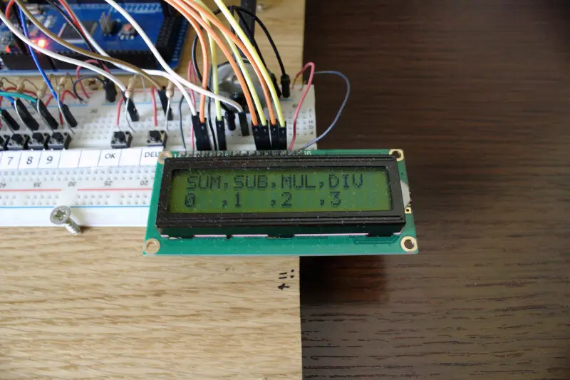
The first screen allows the user to choose one of the four aforementioned mathematical operations. The choice is made by pressing:
- 0, for the addition (ADDition)
- 1 for the subtraction (SUBtraction)
- 2 for the multiplication (MULtiplication)
- 3 for the division (DIVision)
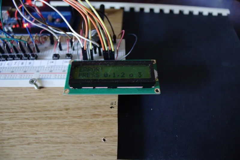
Pressing a key other than these causes the calculator to fail, prompting the user to enter a valid number.
Once the operation has been selected, the calculator allows you to enter the first digit. When you have finished entering the first number you must press the OK key so that the calculator prompts you for the second. When you finish entering the second number, you must press the OK key for the calculator to calculate.
As mentioned above, the number that can be entered can have a maximum of 5 digits. When the user enters a number which has 5 digits the calculator goes to the next step. In the case of the first number, the calculator will ask for the second to be entered. However, if you enter the maximum number of digits while entering the second, the calculator will perform the previously selected calculation. Once the calculator has calculated, the result will remain on the screen until the user presses DEL.
At any time it is possible to press the DEL key to interrupt the current operation and return to the initial screen.
It is not possible to delete the last number or digit entered.


The construction scheme
Below we can observe the schematic Fritzing of the calculator:

Of course the first step is to connect the pushbuttons to create a keyboard. Their connection is very simple and just follow the diagram attached to this step to achieve it.
NOTE: remember that the pushbuttons must necessarily be placed between the two sections of the breadboard to avoid shorting their PINs. So, for this experiment we’ll have to settle for placing the buttons on a line and not on a rectangle.
Not essential but very useful is to write the names of the keys on a piece of paper.
The sketch
Bind pushbuttons to numbers and control keys
The keyboard consists of 12 keys: 10 are required to represent the digits from 0 to 9 while two are used to control operations. Through the definition #define we have associated a specific PIN to each pushbutton.
Pushbuttons are normally open. This means that their default state is LOW and when pressed they go HIGH. It is precisely when the buttons are set to HIGH that a digit (if it is a button used to represent digits) or an event (in the case of the DEL and OK control keys) is associated with this event. We accomplished this with the readKey function.
The two states mentioned above are due to the circuit solution adopted in this scheme. In fact, having a pull down resistor to ground, the pushbutton output level is 0 with the button released (switch open) and 1 (5V) with the button pressed (switch closed).
The keyboard is the tool with which we issue commands to Arduino and for this reason the pushbuttons have been set as INPUT in the void setup () function.
As we know the two basic functions of Arduino are setup and loop. The first is performed only once and essentially checks and/or initializes any components and PINs. The second instead repeatedly executes the code contained in it. So, to block the execution of the loop indefinitely we created the wait function. When the Arduino executes this function it enters a waiting state; in fact it contains only an empty while loop which is true when no key is pressed. When any key is pressed, the Arduino exits this loop by executing the next instruction.
The insertNumb() data entry function
The most complex portion of code is the one contained in the insertNumb function. The main part of this function are the two for loops. The first for loop is dedicated to acquiring the digits of the first number while the second nested for loop is dedicated to acquiring the second.
The number capture function is further complicated by the presence of numerous conditional structures. These structures are needed to manage the acquisition flow. They cause the function to pause when the user presses DEL or to continue when the OK key is pressed. For example, when OK is pressed in the first loop, the conditional structures set the value of counter i to 5. Therefore, the if condition preceding the second for loop becomes true allowing the execution of the second for loop and thus the acquisition of the digits of the second number.
Reading the source code one notices the numerous delays scattered here and there apparently without a precise logic. In reality they are necessary for the synchronization of keyboard reading operations. For example, the first delay inside the insertNumb function is used to prevent the operation selection key from being interpreted as the first digit of the first number.
The loop function
The code inside this function may appear to be complex. What happens is actually quite simple.
The main variable is operation. It can assume only 4 values, corresponding to the aforementioned fundamental operations. Then, depending on the assumed value and thanks to a conditional structure, the algorithm selects the block of code necessary to perform the operation chosen by the user.
Converting a part of the sketch to the library
In the sketch there are some parts that must necessarily be repeated several times. This is due to the nature of the keyboard. For this reason it seemed appropriate to write a library in order to have a cleaner code and the possibility to modify the sketch or add new functions without having to revolutionize the basic code.
We will not explain here how to create a library for Arduino both because there is already an excellent official guide available here and because this would lead to an unnecessary and excessive lengthening of the tutorial.
What we will do is list its functions and the required input parameters. We won’t even explain the methods and what they do because we’ve done it before.
NOTE: the library works only with 16×2 LCD displays therefore it cannot be used to print messages on the serial monitor.
How to use the library
TechrmKeypad is the name of the class.
The first thing we do is to instantiate an object of the class passing it the parameters related to the buttons.
Example
TechrmKeypad keypad (key0, key1, key2, key3, key4, key5, key6, key7, key8, key9, DEL, ENTER);
The following instructions are the available methods:
- keypad.wait(): is a method that returns nothing (void) and takes no parameters
- keypad.readkey(): like the previous method, it returns nothing (void) and takes no parameters
- keypad.insertNumb(&lcd, &control, &error, &number_1, &number_2, &MAXVALUE): this method does not return anything either (void) but takes some parameters as input.
The last method first takes a pointer to an instance of the LCD display class and then pointers to the following global variables:
- control_
- error_
- number_1_
- number_2_
- MAXVALUE
In addition to these methods, you can implement another that incorporates the following lines of code that are repeated many times:
void printOpenmesg (char* myString1, char* myString2) {
    lcd_.clear();
    lcd_.setCursor(0, 0);
    lcd_.print(myString1);
    lcd_.setCursor(0, 1);
    lcd_.print(myString2);
}
Final considerations
At the moment the calculator can only perform the four fundamental operations by taking only two positive and integer numbers as input. By adding more keys, you can make it perform more complex calculations. For example, adding a dedicated key to the comma and one to the “-” sign would make the calculator much more versatile. Or, using the math.h library you could implement many other types of calculations such as logarithms, trigonometric calculations, roots and exponentiations etc.
However, these choices would lead to an extremely more complex code. As we have seen, for only the 4 fundamental operations there are 300 lines of code (500 without the use of any library!).
So, if you are brave enough, feel free to modify our library to add new features or just improve it!
Newsletter
If you want to be informed about the release of new articles, subscribe to the newsletter. Before subscribing to the newsletter read the page Privacy Policy (UE)
If you want to unsubscribe from the newsletter, click on the link that you will find in the newsletter email.
🔗 Follow us on our social channels so you don’t miss any updates!
📢 Join our Telegram channel to receive real-time updates.
🐦 Follow us on Twitter to always stay informed about our news.
Thank you for being part of our TechRM community! 🚀