Introduction
In this tutorial we will see how to solder a 16-pin connector on a 1602A LCD display.
You can see all the projects featured in this blog using this display by going to the link https://www.techrm.com/tag/1602a/.
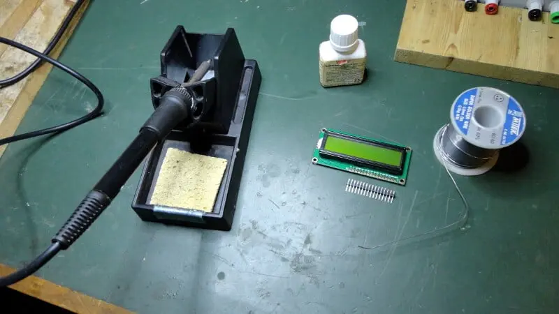
What components do we need for our soldering tutorial diy?
The list of components is not particularly long:
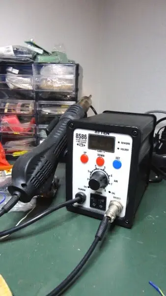
- a soldering iron or soldering station with a very fine tip
- tin, for our purpose 0.8-1 mm in diameter is fine
- liquid flux
- well sharpened nippers
- a magnifying glass (5x is fine)
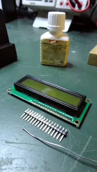
- a 40-pin connector
- a 1602A LCD display
- steady hand and a lot of patience!
In the following video we can see the soldering operation of a connector on the LCD display:


Let’s cut the connector
The first step is to cut the connector to size, which is usually sold with 40 pins.


Tin plating of soldering iron tip and pads
Let’s brush the tip of the soldering iron with the flux brush.
NOTE: this operation must be performed with the soldering iron off (and cold)!
The flux serves two purposes: it prevents oxidation of the tip and helps the solder flow more easily to the solder point.


Let’s regulate the operating temperature
We can now turn on the soldering iron and wait for it to heat up. We have set it to a temperature of around 400°C. This temperature could be high for a beginner, in this case you could set it to a lower temperature.
A lower temperature allows you to linger longer on the soldering point without damaging it. Remember that tin melts at a temperature of around 200-230°C so don’t set it too low.
If you don’t have a soldering station, for small solders like this you can use a normal soldering iron with a power not exceeding 30 or 40W. In general, such a soldering iron warms up in 2-5 minutes.
When the flux stops smoking it’s time to move on to the next step.

Let’s prepare the tip of the soldering iron
It’s time to prepare the soldering iron tip.
The first thing to do is clean the tip of dirt and tin residue from previous soldering. For this operation we will use a natural sponge.
This type of sponge is easily available on the Internet or in specialized shops. The sponge needs to be wet but not soaked, so don’t overdo it with water!
Another thing to avoid is cleaning the tip with metal sponges (like the ones used for washing dishes) or, even worse, using sandpaper.
Abrasive materials remove the thin layer of zinc from the tip and it is instead thanks to this galvanization that the tip remains fully efficient and is able to heat the solder uniformly.
After cleaning it is necessary to tin the tip if you want to get a good result.
Bring the tin close to the tip and spread it evenly but without exceeding the quantity. Otherwise clean the excess by rubbing the tip on the damp sponge.


Soldering
We are finally ready to solder!
Basically this method does not involve direct contact between the solder and the tip of the soldering iron.
Heat each pad of the display with the tip of the soldering iron, indirectly melting the tin. If it does not melt, bring it closer to the tip avoiding direct contact. Observe that some of the solder previously placed on the tip will become part of the material needed for soldering.
Always remember that it is better to put too little tin than too much. It is better to add tin later in case it is insufficient than to have to remove the excess!
Once the first solder is done, check if the connector is perpendicular to the PCB. It is very important to make sure of this to be sure that the connector will fit perfectly on the breadboard.


Quality check
How do you know if a good job has been done? It’s simple: using a magnifying glass!
With the magnifier check your work by comparing your solders with ours, visible in the photo below. A good solder uniformly covers the whole pad and appears shiny: generally these are
the two main indicators of a good solder.
So, if you notice spots where tin is missing, add some to cover the pad completely.
And if the solder doesn’t look shiny, melt the tin again to make it smooth and shiny.
At the end of the operations you will be able to connect your LCD display to Arduino.


Newsletter
If you want to be informed about the release of new articles, subscribe to the newsletter. Before subscribing to the newsletter read the page Privacy Policy (UE)
If you want to unsubscribe from the newsletter, click on the link that you will find in the newsletter email.
🔗 Follow us on our social channels so you don’t miss any updates!
📢 Join our Telegram channel to receive real-time updates.
🐦 Follow us on Twitter to always stay informed about our news.
Thank you for being part of our TechRM community! 🚀