Introduction
This is a simple guide that will teach you how to take the first steps with the BTE13-010 module, a cheap Arduino mini clone. We will go through the 4 basic steps necessary to get it working immediately and without problems:
- connector soldering *
- wiring
- driver installation **
- testing
* Not strictly necessary but very useful if you are planning to use it on a breadboard
** Arduino clones need specific drivers, different from the standard ones that come with the Arduino IDE
What components do we need for our arduino mini clone bte13-010?
The list of components is not particularly long:
- a BTE13-010 module (328p 5V 16Mhz – Arduino mini clone)
- a CH340G module (Serial to USB converter)
- some connectors (typically sold with the BTE13-010)
- some DuPont wires (male – male, male – female, female – female)
- soldering material and equipment (in this regard you can watch our tutorial Yet another tutorial on how to solder)
If you then want to test the module accurately, you can do a simple experiment for which you need:
- a SG90 mini servo motor
- a 2 x 16 LCD display
- a 10 kΩ linear potentiometer or, alternatively, a 10 kΩ resistor (to adjust the display contrast)
Before starting, we specify that this tutorial can be used to learn how to install the drivers of the CH340G module (Serial – USB converter), on which the communication between the Arduino mini and the PC is based.
In the following video you can see the complete servomotor project:
You can download the project from here:
Soldering of the connectors
Necessary steps
Here is a list of the steps required to solder the connectors onto the module:
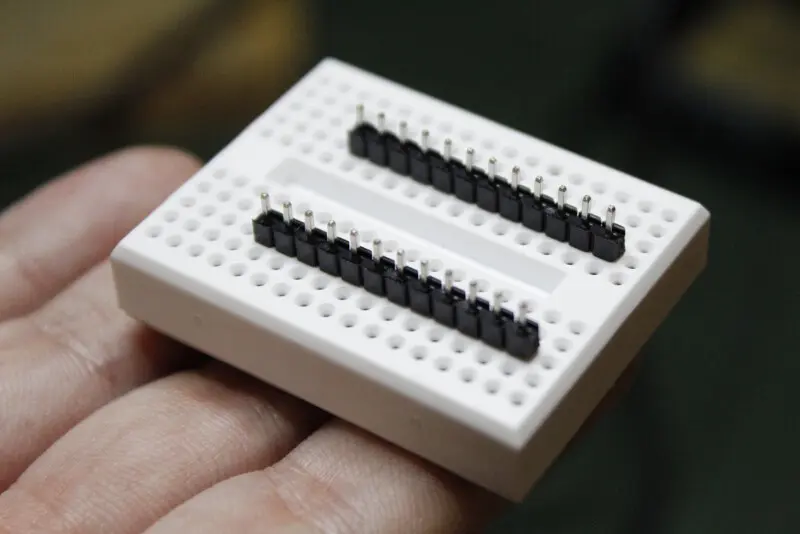
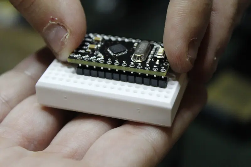
- the operation can be made simpler and more precise with the help of a breadboard. Insert the connectors into the breadboard so that they are perfectly vertical and place the Arduino on them
- brush the pads with flux
- keeping, as already mentioned, the Arduino inserted on the two connectors, solder the 4 pads in the corners. Why only these 4 points? Because the breadboard is made of plastic and excessive heat could damage it
- using a flat blade screwdriver, gently extract the Arduino with the connectors from the breadboard
- continue to solder the other pads, possibly helping yourself with a third hand
- the connector to be soldered on the part of the analog inputs is too wide, thin it slightly by rubbing it on sandpaper
- solder the last connector
Okay, that’s it!
Double check the solders a couple of times and, if everything is fine, go to the next step.


Connection between the BTE13-010 and the CH340G

Look at the Fritzing diagram above or follow the instructions below to connect the Arduino mini clone to the Serial to USB converter:
BTE13-010--------------CH340G
     DTR <-------------> DTR
     TXD <-------------> RXD
     RXD <-------------> TXD
     VCC <-------------> VCC
     GND  NOT CONNECTED  CTS
     GND <-------------> GND
Be careful not to connect the TXD terminal of the BTE13-010 with the TXD terminal of the CH340G (or the two RDX terminals)! To find out why, read this clear guide from Sparkfun on serial port operation and connection.
Also note that the BTE13-010 DTR and GND terminals are printed under the header.

Before connecting the Serial – USB converter, make sure that the switch is positioned on the appropriate voltage value which can be 3.3V or 5V depending on the model of your Arduino. Ours works at 5V and 3.3V interchangeably.

Let’s install the drivers and load the first sketch
This procedure is valid for all Serial – USB converters based on the CH340G USB-to-Serial.
Installing drivers for CH340G on Windows 7
Installing drivers on Windows is very easy, just follow these simple steps:
- download the attached CH341SER.zip file
- unzip it
- double click on the CH341SER.EXE file
To make sure of the perfect success of the operation, go to the Windows device manager and check if you find an item that looks like the one shown in the figure below.
WARNING: by installing a new version of the Arduino IDE you risk overwriting the CH340G drivers. For this reason we suggest you not to install the IDE using the executable (.exe) but to use a “portable” version. If you accidentally overwrite the CH340G drivers, uninstall the IDE with the drivers and reinstall everything from scratch.

Installing CH340G Drivers on Linux (Generic)
In the attached CH341SER_LINUX.ZIP file, there is a file called readme.txt which contains the detail of all the steps to follow. Note that these drivers support a kernel version from 2.6.65 to 3.13.x.
Board setting
Now it’s time to connect the CH340G Serial – USB converter.
Before uploading the sketch, set the correct Arduino model, its microcontroller and the used COM port. See the screenshots below to see where these settings are located.
Obviously set things up consistently with the hardware in your possession!


Let’s load the first sketch
In the IDE, go to File/Examples/Basics/Blink and load the sketch. If you have performed the previous steps correctly, the IDE should be able to communicate with the Arduino and upload the sketch. Eventually you will see LED 13 (on the board, blue) flashing once per second.

We specify that this procedure works with devices that already have a bootloader installed inside them. We have never loaded a bootloader but on the Internet there are many tutorials on the subject, such as:
- https://www.instructables.com/How-To-Burn-a-Bootloader-to-Clone-Arduino-Nano-30/
- https://learn.sparkfun.com/tutorials/installing-an-arduino-bootloader
Controlling a servo motor

The test just carried out makes us understand that our Arduino mini module and the Serial – USB converter work correctly. However, if you want to check the functioning of all (or at least most) of the solders (combining business with pleasure) try this simple experiment.
Our sketch is based on the one found by default on the IDE and which is called “Sweep”, with the addition of a 16×2 LCD display that shows the value of the rotation angle of the servo. Basically, it rotates the servo and shows how much it rotated on the display.
We have powered Arduino by connecting it to a PC (via the Serial – USB CH340G converter) but, if desired, it can be powered with an external power supply; simply set your power supply for an output voltage of 5V and connect the Vcc and GND terminals.
Newsletter
If you want to be informed about the release of new articles, subscribe to the newsletter. Before subscribing to the newsletter read the page Privacy Policy (UE)
If you want to unsubscribe from the newsletter, click on the link that you will find in the newsletter email.
🔗 Follow us on our social channels so you don’t miss any updates!
📢 Join our Telegram channel to receive real-time updates.
🐦 Follow us on Twitter to always stay informed about our news.
Thank you for being part of our TechRM community! 🚀