Introduction
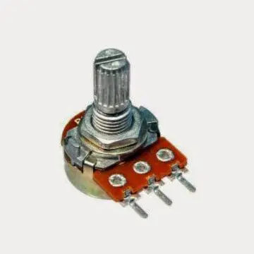
What is a digital potentiometer? We’ve all used a classic potentiometer at least once in our lives: it’s the classic volume knob on our radio! We may not even notice it when instead we are dealing with a digital potentiometer. When on the radio, to vary the volume of the music, we don’t use a knob but + or – buttons, it is probable that they are controlling a digital potentiometer which is nothing more than a potentiometer controlled electronically instead of via a knob.
How does a classic potentiometer work?
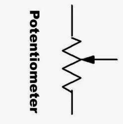
A potentiometer is a 3 terminal device used as a variable resistor. It is equipped with a rotating contact controlled by the knob and is used as a voltage divider.

Its electrical symbol is that of a classic resistor but with the intermediate contact controlled by the knob:

How does a voltage divider work?
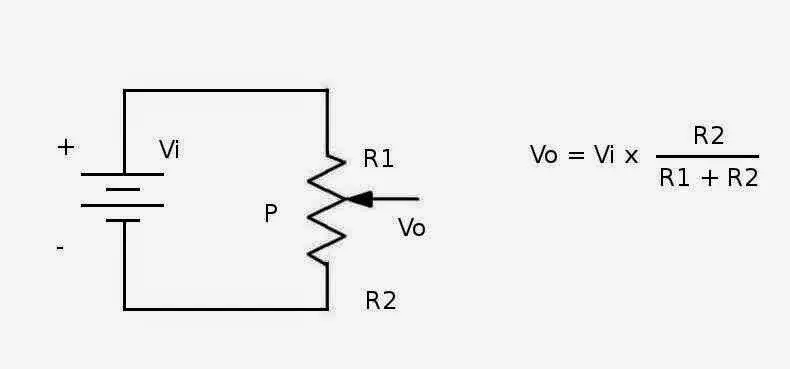
A voltage divider is a simple circuit where the output voltage is a fraction of the input voltage. You can use two fixed resistors or a potentiometer.
Let’s see the scheme and the formula:

The potentiometer is indicated with the letter P while R1 and R2 are the two sections of the total resistance which vary according to the position of the cursor (which is controlled by the knob).
As you can see, the output voltage Vo is a fraction of the input voltage Vi. Vo varies between two extremes:
- Vo = 0 when R2 = 0 (the knob is fully turned towards the terminal connected to the negative pole of the battery)
- Vo = Vi when R1 = 0 (the knob is fully turned towards the terminal connected to the positive pole of the battery)
The digital potentiometers
These examples are based on mechanical potentiometers but there are also commercially available types of potentiometers which are completely electronic and adjustable via a suitable input signal. They are the so-called digital potentiometers.
Today we want to test one by commanding it via Arduino, in particular the MCP41010 model, which is a single potentiometer. Its maximum value is 10 kΩ while the minimum value is about 100 Ω.

Now let’s see the pinout of this component:

The name of the device depends on the maximum resistance value of the single digital potentiometer and on the number of potentiometers inside it. For instance:
- MCP41010: single potentiometer, 10 kΩ
- MCP41050: single potentiometer, 50 kΩ
- MCP41100: single potentiometer, 100 kΩ
- MCP42010: two independent potentiometers, 10 kΩ
- MCP42050: two independent potentiometers, 50 kΩ
- MCP42100: two independent potentiometers, 100 kΩ
To drive our digital potentiometer we will use an Arduino UNO and its SPI port.
Observing the datasheet of the digital potentiometer it can be seen how, to command this chip, it is first necessary to send it a “command byte” (to tell the chip what to do) and then a “data byte” (to tell the chip what resistance value set, from 0 to 255).
For example, to set a resistance of 10 kΩ, we must send a data byte equal to 11111111 (corresponding to 255), to set a resistance of 5 kΩ we must send a data byte equal to 10000000 (corresponding to 128) and so on.
For the command to be executed, first of all the CS terminal must be set to 0 (LOW value) then the command byte must be sent followed by the data byte (for a total of 16 bits). Finally it is necessary to bring the CS terminal back to the value 1 (HIGH value). Only then will the command be executed (from the datasheet: “Executing any command is accomplished by setting CS low and then clocking-in a command byte followed by a data byte into the 16-bit shift register. The command is executed when CS is raised. “)
What components do we need for our digital potentiometer Arduino UNO project?
The list of components is not particularly long:
- a breadboard to connect the Arduino UNO to the other components
- some DuPont wires(male – male, male – female, female – female)
- a digital potentiometer MCP41010
- a 220 Ω resistor
- a red LED
- and, of course, an Arduino UNO board!
Now let’s see the assembly diagram
The purpose of our experiment is to cyclically vary the brightness of the LED by commanding it with Arduino UNO via the MCP41010 digital potentiometer.
Now let’s connect our test circuit as shown in the figure below:

and load the sketch into our Arduino UNO which can be downloaded from here:
Let’s analyze the code
Initially we set the pins of the SPI port related to the CS, CLK and MOSI signals. Then we set the command byte and the initial brightness value of the LED:
int CS_signal = 2;                      // Chip Select signal onsul pin 2 of Arduino
int CLK_signal = 4;                     // Clock signal on pin 4 of Arduino
int MOSI_signal = 5;                    // MOSI signal on pin 5 of Arduino
byte cmd_byte2 = B00010001 ;            // Command byte
int initial_value = 100;                // Setting up the initial value
We then define the initialize function which sends the command byte and the initial value to the digital potentiometer via the SPI port (practically initializes it):
void initialize() {                     // send the command byte of value 100 (initial value)
    spi_out(CS_signal, cmd_byte2, initial_value);
}
We then define two functions (spi_out and spi_transfer) which send the commands and values to the digital potentiometer (again via the SPI port):
void spi_out(int CS, byte cmd_byte, byte data_byte){                        // we need this function to send command byte and data byte to the chip

    digitalWrite (CS, LOW);                                                 // to start the transmission, the chip select must be low
    spi_transfer(cmd_byte); // invio il COMMAND BYTE
    delay(2);
    spi_transfer(data_byte); // invio il DATA BYTE
    delay(2);
    digitalWrite(CS, HIGH);                                                 // to stop the transmission, the chip select must be high
}

void spi_transfer(byte working) {
    for(int i = 1; i <= 8; i++) {                                           // Set up a loop of 8 iterations (8 bits in a byte)
     if (working > 127) {
       digitalWrite (MOSI_signal,HIGH) ;                                    // If the MSB is a 1 then set MOSI high
     } else {
       digitalWrite (MOSI_signal, LOW) ; }                                  // If the MSB is a 0 then set MOSI low

    digitalWrite (CLK_signal,HIGH) ;                                        // Pulse the CLK_signal high
    working = working << 1 ;                                                // Bit-shift the working byte
    digitalWrite(CLK_signal,LOW) ;                                          // Pulse the CLK_signal low
    }
}
In the setup function we set the digital pins, previously defined, as OUTPUT, we initialize the digital potentiometer and the serial port:
pinMode (CS_signal, OUTPUT);
pinMode (CLK_signal, OUTPUT);
pinMode (MOSI_signal, OUTPUT);

initialize();

Serial.begin(9600);                                                     // setting the serial speed
Serial.println("ready!");
In the loop function there are two “for loops”: the first gradually increases the resistance in series with the LED, the second gradually decreases the resistance in series with the LED.
for (int i = 0; i < 255; i++) {
    spi_out(CS_signal, cmd_byte2, i);
    Serial.println(i); delay(10);
}
for (int i = 255; i > 0; --i) {
    spi_out(CS_signal, cmd_byte2, i);
    Serial.println(i);
    delay(10);
}
The result is that the LED turns on and off gradually (as can be observed from the video below):
Final considerations
As you can see, the presented circuit is very simple but it is enough to show the usefulness of these devices. Obviously we could have driven the LED, always cyclically varying its brightness, via a PWM signal but this was not the purpose of our tutorial. A possible use of this potentiometer is coupled with an operational amplifier, with which we can create signal amplifiers or active filters controlled electronically (and not by knob).
External Resources
For more informations see also:
https://nicksen782.blogspot.it/2010/06/digital-potentiometers-mcp42010.html
Newsletter
If you want to be informed about the release of new articles, subscribe to the newsletter. Before subscribing to the newsletter read the page Privacy Policy (UE)
If you want to unsubscribe from the newsletter, click on the link that you will find in the newsletter email.
🔗 Follow us on our social channels so you don’t miss any updates!
📢 Join our Telegram channel to receive real-time updates.
🐦 Follow us on Twitter to always stay informed about our news.
Thank you for being part of our TechRM community! 🚀