Introduction
Arduino Cloud is a web platform that serves to connect with devices such as Arduino, NodeMCU and so on in order to collect the data sent by them and display it on a dashboard. It also allows you to control these devices by specific commands on the dashboard. It also has the possibility of automatically generating the sketches to be loaded on the board already correctly configured.
You need to create your own account in order to access it and start creating your own objects (called things in the platform). In short, with Arduino Cloud we can create real IoT (Internet of Things) projects.
What will we do in this project?
We will create a simple circuit composed of an ESP8266 NodeMCU, a 4.7kΩ resistor and a DHT22 sensor which will detect the ambient temperature and humidity at regular intervals. However, this data will not be displayed on an LCD display or saved on an SD card (as we have done in the articles How to make a bluetooth datalogger for temperature and humidity using Arduino MEGA and Thermo-hygrometer with clock and LCD display on Arduino UNO) but will be sent to the Arduino Cloud.
On this cloud we will therefore create an object (or thing) capable of reading the data sent by our NodeMCU board and displaying them on its dashboard in a graphical way.
The platform will generate the basic sketch automatically, we will take it and create a project on PlatformIO starting from it in order to free ourselves from the platform and use it only for data collection and visualization. We will complete the cloud-generated code with the part that manages the DHT22 sensor and makes the temperature and humidity measurements.
What components do we need for our ESP8266 Arduino Cloud datalogger project?
The list of components is not particularly long:
- a breadboard to connect the NodeMCU ESP8266 board to the other components
- some DuPont wires (male – male, male – female, female – female)
- a DHT22 sensor
- a 4.7kΩ resistor
- and, of course, a NodeMCU ESP8266 board!
Project realization
The wiring diagram
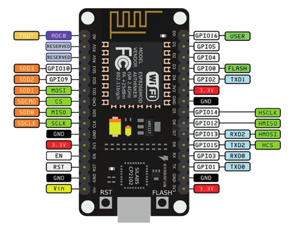
Before realizing the actual circuit let’s look at the pinout of the board:

We will use the GPIO 14 (labeled D5 on the board) to connect the DHT22 sensor.
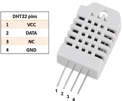
While the DHT22 sensor pinout is as follows:

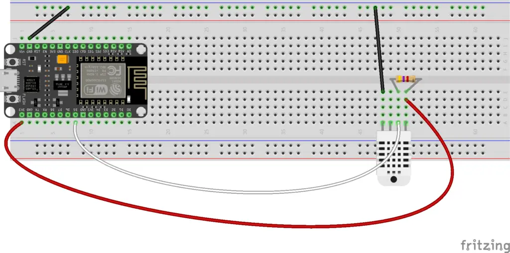
Below there is the wiring diagram created using Fritzing:

As you can see, the power for the DHT22 is taken from the 3.3V output of the NodeMCU (pin 3V3). It is necessary to power the sensor with 3.3V so that its output is also 3.3V as the digital pins of the NodeMCU do not accept voltages higher than 3.3V.
WARNING: in the ESP8266 NodeMCU the maximum voltage tolerated by the digital inputs is equal to 3.3V. Any higher voltage would damage it irreparably!!
The output pin is connected to the power supply via a 4.7kΩ pull-up resistor and then, via the white wire, to pin D5 (which corresponds to GPIO14).
Let’s create the objects and the dashboard on the Arduino Cloud
First, if you haven’t already done so, you need to create an account on the Arduino Cloud. Once you have logged in you will find this page:

Click on the GET STARTED button and you will be sent to the page:

Click on the IoT Cloud button. The Things page will open.
At this point you will proceed to:
- create the device that will map the board
- create the object (thing) with the variables (temperature and humidity) to be detected and displayed on the dashboard associated with the device created in the previous step
- create the dashboard to be associated with the variables detected by the object
We can see the procedure just listed on this video:
PLEASE NOTE: it is important to note that at 1:06 I downloaded a pdf containing the connection parameters to the device. They are called Device ID and Secret Key and we will need them later. So download this pdf and keep it somewhere.
Obviously the Device ID and Secret Key parameters are specific to each device, therefore they change when the device changes.
Once the procedure is complete, go to the test_thing object and click on the Sketch tab:

Then press the Open full editor button:

A window like this will open:

What interests us (and which we will use later) are the main .ino file (the one called test_thing_feb15b.ino in the photo and which will have a different name from you) and the thingProperties.h file. We will use these two files later in our PlatformIO project.
Let’s create the PlatformIO project
We have already seen the procedure for creating a PlatformIO project in the article How to create a project for NodeMCU ESP8266 with PlatformIO. Of the libraries indicated, install, following the procedure, the DHT sensor library for ESPx by Bernd Giesecke (which is used to read the data transmitted by the DHT22 temperature and humidity sensor) and leave the other two alone (WiFiManager and UniversalTelegramBot).
Instead, always following the usual procedure, install the Arduino_ConnectionHandler library:

and the ArduinoIoTCloud library:

For now, the platformio.ini file should look like this (the versions of the libraries may eventually change):
[env:nodemcuv2]
platform = espressif8266
board = nodemcuv2
framework = arduino
lib_deps =
	arduino-libraries/Arduino_ConnectionHandler@^0.7.3
	arduino-libraries/ArduinoIoTCloud@^1.10.0
        beegee-tokyo/DHT sensor library for ESPx@^1.18
At this point go back to the cloud platform, copy the contents of the .ino file:

and paste it into the main.cpp file of the PlatformIO project, in order to completely replace its contents.
Now create in the include folder a file that you will call thingProperties.h, go to the cloud platform, copy the content of the tab thingProperties.h:

and paste it into the thingProperties.h file you just created in the include folder.
At this point you will have to edit this file in order to connect it to the cloud:
const char DEVICE_LOGIN_NAME[]  = "4da2b100-b400-4b54-9c97-645a3d048b3a";

const char SSID[]               = SECRET_SSID;    // Network SSID (name)
const char PASS[]               = SECRET_OPTIONAL_PASS;    // Network password (use for WPA, or use as key for WEP)
const char DEVICE_KEY[]  = SECRET_DEVICE_KEY;    // Secret device password
As you can see, in this section there are some parameters to set.
The first parameter (DEVICE_LOGIN_NAME) was automatically added and you can find it in the pdf you downloaded when you created the object (you can find the reference in the previous video). In the pdf the parameter is called Device ID.
The SECRET_SSID and SECRET_OPTIONAL_PASS parameters are, respectively, the name and password of your WiFi network. Therefore, instead of SECRET_SSID you will put the name of your network between double quotes (“) and instead of SECRET_OPTIONAL_PASS you will put your network password (always between double quotes).
The last parameter, SECRET_DEVICE_KEY, can always be found in the pdf you downloaded from the platform with the name Secret Key.
So the section in question should look like this:
const char DEVICE_LOGIN_NAME[]  = "4da2b100-b400-4b54-9c97-645a3d048b3a";
const char SSID[]               = "test_cloud";    // Network SSID (name)
const char PASS[]               = "5ty513y8o9";    // Network password (use for WPA, or use as key for WEP)
const char DEVICE_KEY[]  = "TYWLGFTYNMKNV8UGCYRA";    // Secret device password
Let’s edit the main.cpp and platformio.ini files
Now add to the platformio. ini the lines:
monitor_speed = 115200
upload_speed = 921600
so that it looks like this:
[env:nodemcuv2]
platform = espressif8266
board = nodemcuv2
framework = arduino
monitor_speed = 115200
upload_speed = 921600
lib_deps =
	arduino-libraries/Arduino_ConnectionHandler@^0.7.3
	arduino-libraries/ArduinoIoTCloud@^1.10.0
	beegee-tokyo/DHT sensor library for ESPx@^1.18
At this point you will have to make changes to the main.cpp file in order to add the parts that manage the DHT22 sensor.
#include "DHTesp.h"
DHTesp dht;
#define  DHT22_PIN 14
Add these lines right after the includes. With this piece of code we include the DHT22 library, instantiate the dht object and define pin 14 (GPIO14) for sensor reading.
In the setup function edit the line:
Serial.begin(9600);
to:
Serial.begin(115200);
and add this line at the end of the function:
dht.setup(DHT22_PIN, DHTesp::DHT22); // Connect DHT sensor to GPIO 14 (D5)
which connects the DHT22 sensor to the GPIO14 so they can communicate.
In the loop function add these lines:
delay(dht.getMinimumSamplingPeriod());

humidity = dht.getHumidity();
temperature = dht.getTemperature();

Serial.println(temperature);
Serial.println(humidity);
which are used to read from the sensor and to put the acquired values in the temperature and humidity variables so that they can be sent to the cloud.
You can download the project from the link below:
Now compile the project and upload it to the board. If all went well you should see the temperature and humidity measurements on the Arduino Cloud dashboard, as shown in the following video:
Newsletter
If you want to be informed about the release of new articles, subscribe to the newsletter. Before subscribing to the newsletter read the page Privacy Policy (UE)
If you want to unsubscribe from the newsletter, click on the link that you will find in the newsletter email.
🔗 Follow us on our social channels so you don’t miss any updates!
📢 Join our Telegram channel to receive real-time updates.
🐦 Follow us on Twitter to always stay informed about our news.
Thank you for being part of our TechRM community! 🚀