Introduction
In this article we will explore one of the elements of the Arduino Cloud dashboard: the scheduler. We will use this element to command a red LED driven by our ESP8266 NodeMCU. We will use, as always, our favorite IDE: Platformio.
In the age of the Internet of Things (IoT), automation plays a crucial role in optimizing daily activities. Imagine being able to control your connected devices automatically, without having to intervene manually every time. In this guide, we will explore one of the most powerful features offered by the Arduino Cloud platform: the scheduler. We will learn how to exploit this feature to orchestrate the behavior of an LED, allowing it to turn ON and OFF in a scheduled and automatic way. We will learn how to program an LED to turn ON and OFF at predefined times. This same logic can obviously be extended to more complex devices, such as electric stoves or water heaters, using relays for power management. This practical example illustrates how automation, enabled by the marriage of technology and creativity, can simplify and improve the control of IoT devices, paving the way for greater efficiency and flexibility in daily operations.
We have already seen how to drive two red LEDs via the Arduino Cloud dashboard in the article How to create a remote control system of two LEDs with ESP8266,Arduino Cloud and PlatformIO so I suggest you go and have a look at it.
What is Arduino Cloud?
Arduino Cloud is a powerful cloud-based platform that allows you to connect and manage your Arduino devices (and more) through the Internet. It is designed to simplify the interaction between physical devices and the digital world, offering advanced remote management, monitoring and control capabilities.
Arduino Cloud provides an intuitive and user-friendly interface that allows you to create custom dashboards (as in our case to control a circuit with LEDs via a scheduler). This means that, through a web interface or a mobile application, it is possible to access the dashboard and interact with the connected devices, without the need to manually program or configure the microcontroller.
Through Arduino Cloud, it is possible to monitor the status of the devices, send commands and receive data in real time. This opens up a wide range of possibilities for automation, remote monitoring and control of systems based on Arduino, NodeMCU and so on.
In essence, the Arduino Cloud is a complete solution for device connectivity, management and control, providing a simple and intuitive experience for remote monitoring and control. With its ease of use and the power of its features, the Arduino Cloud makes it possible to create interactive and connected systems that can be controlled and managed anywhere there is an Internet connection.
What components do we need for our Arduino Cloud Scheduler project with ESP8266 and PlatformIO?
The list of components is not particularly long:
- a breadboard to connect the NodeMCU ESP826 to other components
- some DuPont wires (male – male, male – female, female – female)
- one 100Ω resistor
- one red LED
- and, of course, a NodeMCU ESP826 !
Project realization
The wiring scheme
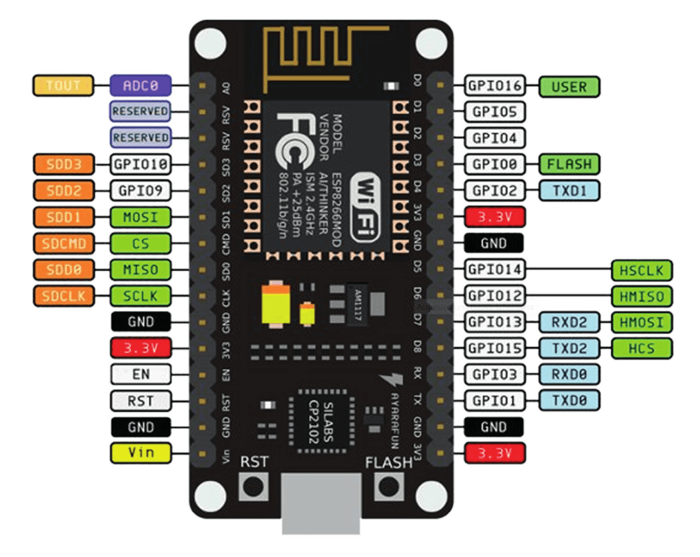
Before realizing the actual circuit let’s look at the pinout of the board:

We will use GPIO 4 to connect the LED. The LED can only be ON or OFF depending on the status of the scheduler. It will be driven by the ESP8266 with a boolean signal (true/false).
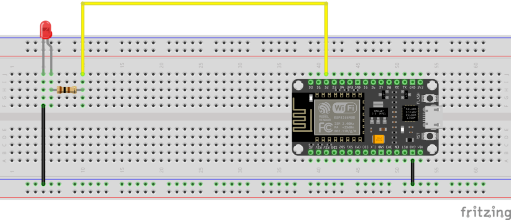
At this point you can proceed with the creation of the circuit by following the connection diagram below.
The LED is connected to the ESP32 via a 100Ω resistor to limit the current flowing through it and avoid burning it (and burning the digital output to which it is connected).
The LED has two terminals (called anode and cathode) and, like all diodes, it is a component that has its own polarity: it passes the current when it is forward polarized (i.e. the voltage at the anode is greater than that at the cathode) and it blocks current when it is reverse polarized (i.e. the anode voltage is lower than the cathode voltage). The voltage between the anode and cathode, which we will indicate with Vd, varies according to the color of the light emitted. In particular we have that:
- Vd = 1.8 V for red LEDs
- Vd = 1.9 V for yellow LEDs
- Vd = 2 V for green LEDs
- Vd = 2 V for orange LEDs
- Vd = 3 V for blue LEDs
- Vd = 3 V for white LEDs
Below is the wiring diagram created with Fritzing:

How do we identify the anode and cathode of the LED? We do this by looking at its terminals. The longest corresponds to the anode. Also, the LED body has a flattening at one point on the edge indicating that the nearby terminal is the cathode.
So if an LED doesn’t light up it’s possible that it’s wired upside down. In this case, to make it work, simply reverse the connections.
How do you calculate the resistance to connect to the LED?
Please note: this paragraph deals with the calculation of the limiting resistance in a theoretical way and requires a minimum knowledge of the basics of Electrotechnics. Therefore it is not essential for understanding the rest of the project and can be skipped by the reader not interested in such theoretical aspects.
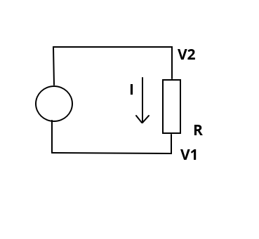
As we have already said, the resistor between the generic GPIO and the LED serves to limit the current flowing through the LED. But how can we calculate its resistance value? Ohm’s Law comes to our aid which says that the potential difference across a resistor (i.e. the voltage measured at the ends of the resistor) is proportional to the current I flowing through it and the constant of proportionality is precisely the resistance value of the resistor R:
V2 - V1 = RIPlease note: for the sake of precision it must be pointed out that while the resistor is the physical component (the actual object), the resistance is its value. So it is improper (even if it happens frequently) to call the resistor with the term resistance.
We can see Ohm’s Law on a simple circuit consisting of a voltage source (the circle on the left) and a resistor:

The voltage (or potential difference) V2 – V1 impressed by the voltage source on the resistor is equal to the product of R by I.
Now let’s see a slightly more complex scheme where the usual voltage generator, the resistor and a red LED are present:

In our case the Vg represents the voltage present at the digital output of the ESP32 when it is HIGH and is therefore equal to 3.3V.
Vd is the voltage across the diode (between anode and cathode) when it is forward biased (ie when it is carrying current). Having chosen a red LED, we know from the previous table that Vd = 1.8V.
We need to determine the R-value of the resistor. We still have one unknown: the value of the current I which must flow in the circuit when the pin is in the HIGH state.
Please note: when the digital pin is in the LOW state its voltage (ie Vg) is zero, it follows that also the current I in the circuit is zero.
LEDs generally cannot withstand currents greater than 20mA, so we impose a maximum current of 15mA to be on the safe side.
By Kirchhoff’s voltage law we have that:
Vg - Vr - Vd = 0From which we derive that:
Vr = Vg - Vd Passing to the real values, we have that:
Vr = 3.3V - 1.8VIt follows that:
Vr = 1.5VBut, by Ohm’s Law, we have that:
Vr = RIfrom which:
R = Vr / ISubstituting the real values:
R = 1.5V / 0.015AThe result is a value of R equal to 100Ω.
Let’s create the objects and the dashboard on the cloud
First, if you haven’t already done so, you need to create an account on the Arduino Cloud. Once you have logged in you will find this page:

Click on the GET STARTED button and you will be sent to the page:

Click on the IoT Cloud button. The Things page will open.
At this point you will proceed to:
- create the device that will map the board
- create the object (thing) with the variables (Schedule and Status) associated with the device created in the previous step
- create the dashboard to be associated with the variables
We will see the procedure just listed with this video:
PLEASE NOTE: it is important to note that in the video, at the minute 2:06, I have downloaded a pdf containing the connection parameters to the device. They are called Device ID and Secret Key and we will need them later. So download this pdf yourself and keep it somewhere.
Obviously the Device ID and Secret Key parameters are specific to each device, therefore they change when the device changes.
Once the procedure is complete, go to the test_thing object and click on the Sketch tab:

Then press the Open full editor button:

A window like this will open:

What interests us (and which we will use later) are the main .ino file (the one called test_thing_aug08a.ino in the photo and which will have a different name from you) and the thingProperties.h file. We will use these two files later in our PlatformIO project.
Let’s create the PlatformIO project
We have already seen the procedure for creating a PlatformIO project in article How to create a project for NodeMCU ESP8266 with PlatformIO
Do not install the libraries indicated in that article because we don’t need them in this project. Instead, always following the usual procedure, install the Arduino_ConnectionHandler library:

and the ArduinoIoTCloud library:

Now edit the platformio.ini file to add these two lines:
monitor_speed = 115200
upload_speed = 921600
so that it looks like this:
[env:nodemcuv2]
platform = espressif8266
board = nodemcuv2
framework = arduino
monitor_speed = 115200
upload_speed = 921600
lib_deps =
	arduino-libraries/Arduino_ConnectionHandler@^0.7.3
	arduino-libraries/ArduinoIoTCloud@^1.10.0
At this point go back to the cloud platform, copy the contents of the .ino file:

and paste it into the main.cpp file of the PlatformIO project, in order to completely replace its contents.
Now create in the include folder a file that you will call thingProperties.h, go to the cloud platform, copy the content of the tab thingProperties.h:

and paste it into the thingProperties.h file you just created inside the Platformio project.
At this point you will have to edit this file in order to connect it to the cloud:
const char DEVICE_LOGIN_NAME[]  = "XXXXXXXXXXXXXXXXXXXXXXXXXX";

const char SSID[]               = SECRET_SSID;    // Network SSID (name)
const char PASS[]               = SECRET_OPTIONAL_PASS;    // Network password (use for WPA, or use as key for WEP)
const char DEVICE_KEY[]  = SECRET_DEVICE_KEY;    // Secret device password
As you can see, in this section there are some parameters to set.
The first parameter (DEVICE_LOGIN_NAME) was automatically added and you can find it in the pdf you downloaded when you created the object (you can find the reference in the previous video). In the pdf the parameter is called Device ID.
The SECRET_SSID and SECRET_OPTIONAL_PASS parameters are, respectively, the name and password of your WiFi network. Therefore, instead of SECRET_SSID you will put the name of your network between double quotes (“) and instead of SECRET_OPTIONAL_PASS you will put your network password (always between double quotes).
The last parameter, SECRET_DEVICE_KEY, can always be found in the pdf you downloaded from the platform with the name Secret Key.
So the section in question should look like this:
const char DEVICE_LOGIN_NAME[]  = "5b20cc94-d4fe-4d09-a4fa-7bb75e353aa7";
const char SSID[]               = "my_wifi_network_ssid";    // Network SSID (name)
const char PASS[]               = "my_wifi_network_password";    // Network password (use for WPA, or use as key for WEP)
const char DEVICE_KEY[]  = "P7WPMDDR2G9SZW2LKBAY";    // Secret device password
As you can see, I put in the DEVICE_LOGIN_NAME field the value taken from the pdf under Device ID (in this case 5b20cc94-d4fe-4d09-a4fa-7bb75e353aa7), in the SSID field the SSID of my WiFi network (in this case my_wifi_network_ssid), in the PASS field the password of my WiFi network (in this case my_wifi_network_password) and in the DEVICE_KEY field the value taken from the pdf under the Secret Key (in this case P7WPMDDR2G9SZW2LKBAY).
It’s time to edit the main.cpp file.
You will initially include the Arduino library and the thingProperties.h file like this:
#include <Arduino.h>
#include <thingProperties.h>
Next you will define the digital pin that will drive the LED:
#define BOOL_LED_PIN_PIN 4
In the setup function, change the speed of the serial port from 9600 to 115200:
Serial.begin(115200);
instead of:
Serial.begin(9600);
Then initialize the status variable to false:
status = false;
At the end of the setup function define the pin as output:
pinMode(BOOL_LED_PIN_PIN, OUTPUT);
Now update the loop function with this code:
void loop() {
  ArduinoCloud.update();
  // Your code here
  if (schedule.isActive()) {
    // whenever the job is "active", turn on the LED
    status = true;      // status true turns ON the LED on the dashboard
    Serial.println(status);
    digitalWrite(BOOL_LED_PIN_PIN, HIGH);
  } else {
    // whenever the job is "not active", turn off the LED
    status = false;      // status false turns OFF the LED on the dashboard
    Serial.println(status);
    digitalWrite(BOOL_LED_PIN_PIN, LOW);
  }
}
As you can see there is an if block whose condition depends on the value assumed by the schedule variable. This variable is directly controlled by the scheduler on the Dashboard (a scheduler that you have previously set to make the LED turn ON at a certain date and time, for a certain time interval, on certain days of the week). When the scheduler on the Dashboard activates this variable (depending on the timing set on it), the condition is met.
When the condition in the if is true, the status variable (which controls the LED on the Arduino Cloud Dashboard) is set to true (making the LED on the Dashboard turn ON). At the same time the BOOL_LED_PIN_PIN pin is set to HIGH, causing the physical LED connected to the ESP8266 to turn ON.
Conversely, when the condition in the if is not verified, the status variable (which controls the LED on the Arduino Cloud Dashboard) is set to false (making the LED on the Dashboard go OFF). At the same time the BOOL_LED_PIN_PIN pin is set to LOW, causing the physical LED connected to the ESP8266 to turn OFF.
Of course you can download the project from the following link:
Let’s see our scheduler in action
Now compile the project and upload it to the board. If all went well you should see how the LED behaves when you operate the dashboard controls, as shown in the following video:
As you can see I set the start time of the LED connected to the ESP8266 and the one on the Dashboard at 20:09 and I set the duration of the LED to one minute with daily repetition. You will notice that the LEDs will turn on at 0:52 and turn off at 1:52.
Newsletter
If you want to be informed about the release of new articles, subscribe to the newsletter. Before subscribing to the newsletter read the page Privacy Policy (UE)
If you want to unsubscribe from the newsletter, click on the link that you will find in the newsletter email.
🔗 Follow us on our social channels so you don’t miss any updates!
📢 Join our Telegram channel to receive real-time updates.
🐦 Follow us on Twitter to always stay informed about our news.
Thank you for being part of our TechRM community! 🚀