Introduction
We have already seen how to make a simple video surveillance system with the Freenove ESP32-WROVER CAM Board with camera in the article How to create a simple video surveillance system with ESP32 on PlatformIO.
In that project the board sends us the images, through an embedded web server, to a certain URL that can be opened with our browser.
What we would like to do in this article is to create a project where the board, connected to the WiFi network, can be controlled remotely via a Telegram bot. This will allow us to send a command to the bot and get a photo taken by our Freenove as a response. Furthermore our device will be equipped with an ultrasonic sensor HC-SR04 used as a detector of the presence of a possible intruder. When the sensor detects the presence of a person or, in any case, of something moving, it will give the command to take a photo to our board which will send it to us via the bot.
The HC-SR04 ultrasonic sensor, which we have already used in article Ultrasonic distance meter with LCD display on Arduino UNO, essentially behaves like a sonar: it emits a high-frequency sound, far beyond what the human ear can hear, and waits for the echo.
Once the echo has been captured, it counts the time elapsed between the emission of the ultrasonic signal and the capture of its echo, and on the basis of this it calculates, knowing the speed of sound in the air, the approximate distance of the object it has produced the echo.
The presence detection function can always be activated or deactivated via a command sent with the Telegram bot. However, it will always be possible to take pictures manually, via a proper command to the bot. This setting will be saved on the EEPROM memory of the board in order to keep it even if there is a power failure. To know how EEPROM memory works you can take a look at the tutorial How to use the EEPROM memory on the NodeMCU ESP8266. Even if it refers to the ESP8266 NodeMCU board, it is also good for the one covered by this tutorial.
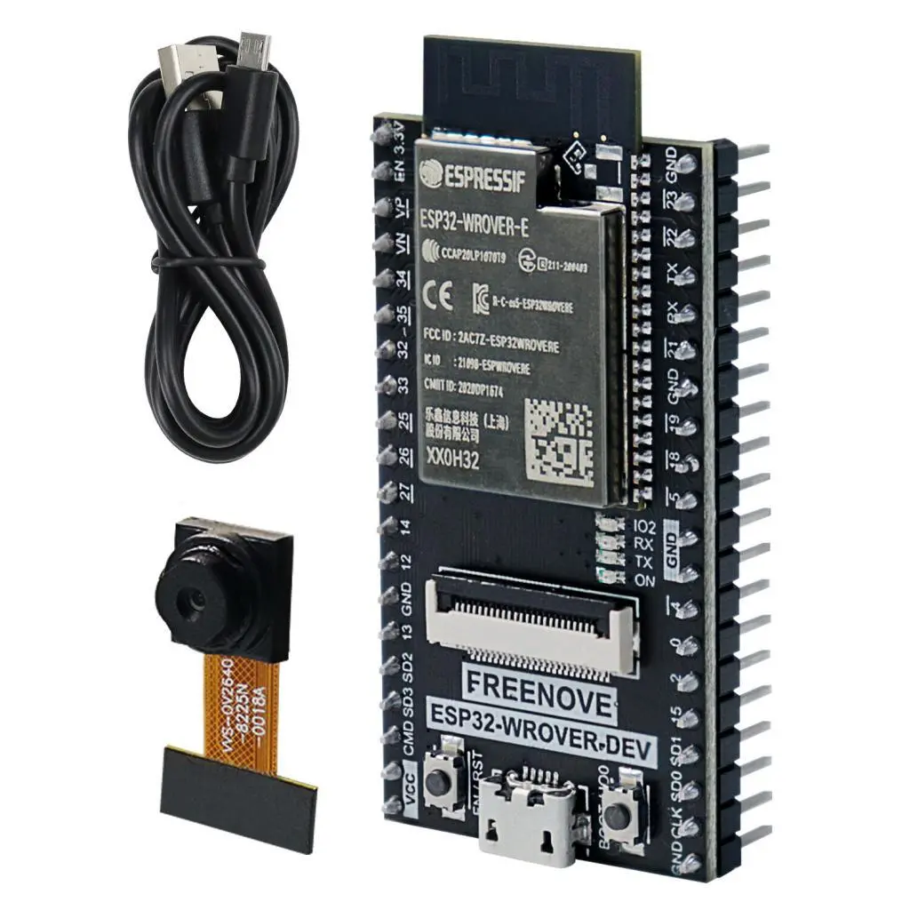
What components do we need for our Telegram-controlled video surveillance project with ESP32 and PlatformIO?
The list of components is not particularly long:
- a breadboard to connect the Freenove ESP32-WROVER CAM Board with camera to the other components
- some DuPont wires (male – male, male – female, female – female)
- a HC-SR04 module
Let’s make the project
The wiring scheme
Let’s first see the pinout of our board:
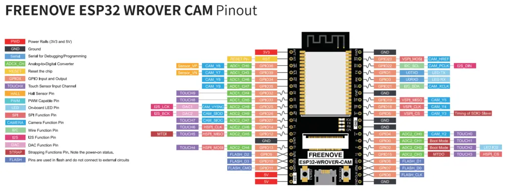
Not all pins will be usable freely as they are used by the camera (those marked with light blue labels starting with CAM). The GPIOs we will be using in this project are 32 and 33, which are not used by the camera.
Below you can see the Fritzing wiring scheme:
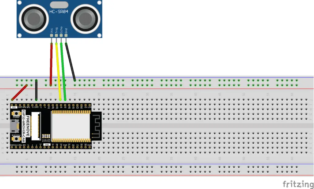
The power supply of the ultrasound module is obtained from the VCC and GND pins of the board, while terminals for the trigger and the echo are connected respectively to pins 33 and 32 of the Freenove.
Let’s create the project for the sketch on PlatformIO
We have already seen in a previous article how to create a project using the excellent PlatformIO IDE. So let’s create our project by following the instructions in the article How to create a project for NodeMCU ESP8266 with PlatformIO. Although it refers to the ESP8266 board, the procedure is similar. Simply, in choosing the platform we will have to choose the Espressif ESP-WROVER-KIT.
Of the libraries described in the article, we only install the UniversalTelegramBot as we will add the other one we need (WifiManager) in a different way.
The platformio.ini file, which you will find in the project downloadable from the link below, must be modified so that it contains the following lines (after the commented header):
[env:esp-wrover-kit]
platform = espressif32
board = esp-wrover-kit
framework = arduino
monitor_speed = 115200
upload_speed = 921600
board_build.partitions = huge_app.csv
build_flags = -DBOARD_HAS_PSRAM
lib_deps =
	https://github.com/tzapu/WiFiManager.git
	witnessmenow/UniversalTelegramBot@^1.3.0
With these settings we are defining the platform (esp-wrover-kit), the speed of the Serial Monitor (115200), the loading speed of the sketch (921600), the type of memory partition to use (huge_app.csv), the presence of a PSRAM (-DBOARD_HAS_PSRAM), the UniversalTelegramBot library and the WiFiManager library directly from its repository (https://github.com/tzapu/WiFiManager.git).
Obviously we also need the project, which can be downloaded from the link below:
Overwrite the main.cpp file with the one you just downloaded and copy the app_httpd.cpp file into the src folder and the camera_index.h and camera_pins.h files in the include folder.
How to connect the board to the Internet
After uploading the sketch to the board, open the Serial Monitor to see the messages coming from the device.
First the board goes into Access Point mode and will give us an IP address which we will use shortly. This operation is used to connect the board to the Internet without having to enter the WiFi network parameters (SSID and password) in the code.

In this case the IP address is 192.168.4.1.
At this point the Freenove is in Access Point mode (with SSID AutoConnectAP) and we need to connect our computer to the AutoConnectAP network. If we go to the networks menu of our computer, we should also see the AutoConnectAP network in the list of wireless networks.
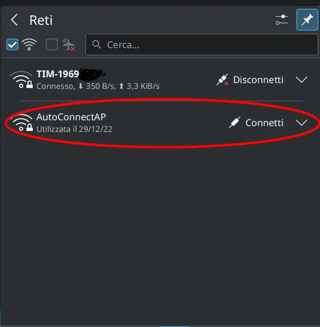
Connect the computer to the AutoConnectAP network. Then go to your browser and enter the IP previously provided by Freenove: 192.168.4.1
You will see a screen like this:
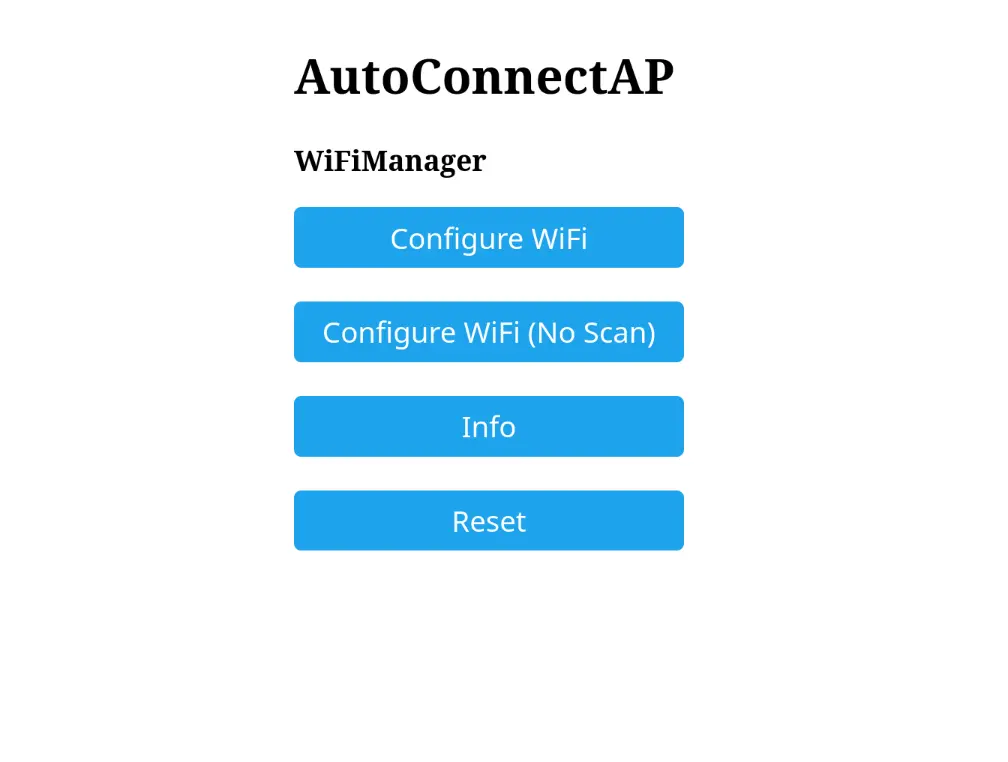
Click the ConfigureWiFi button. It will show you the available networks:
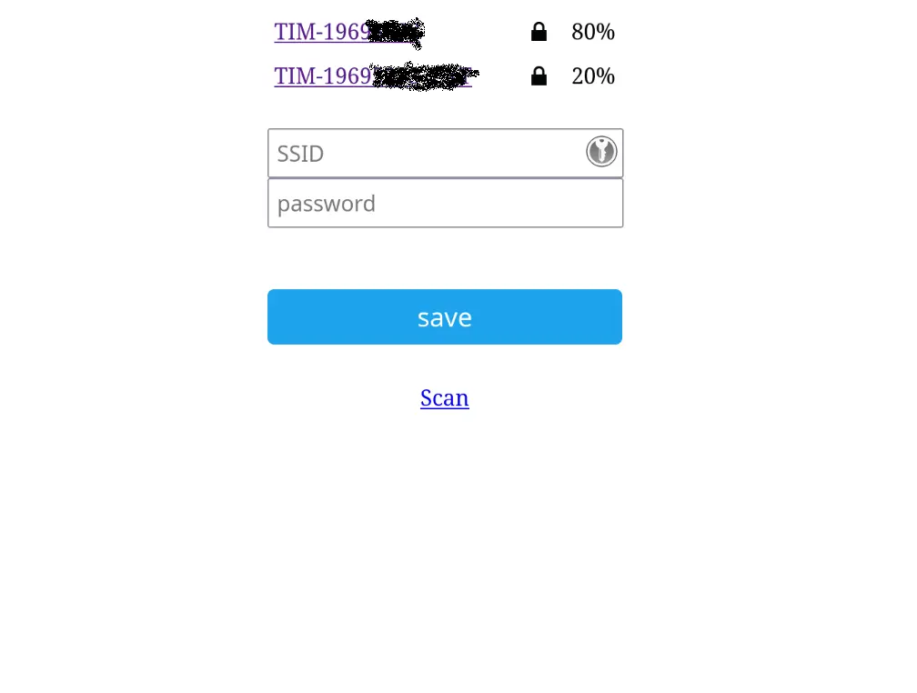
Choose the SSID of your network:
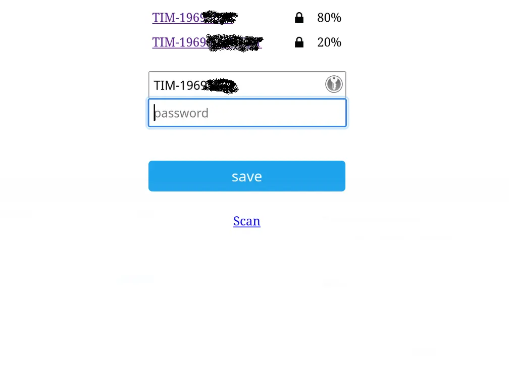
Enter your network password and click the save button:
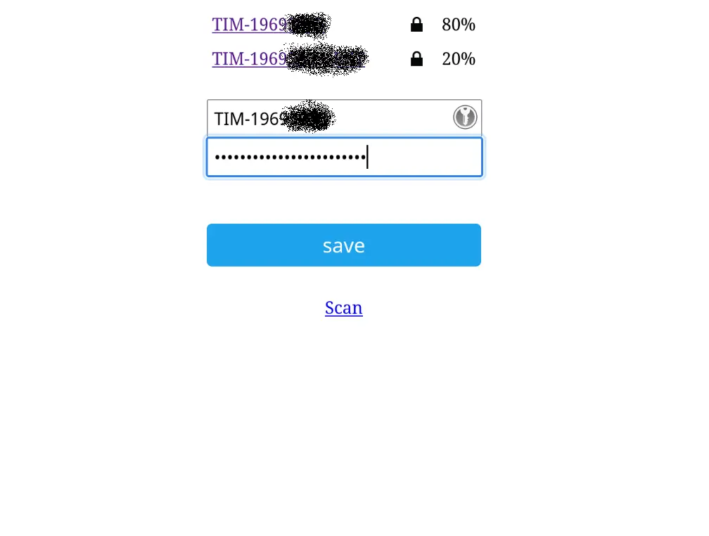

The Freenove module keeps the login parameters memorized even if you turn it off, it will remember them when you will restart it and it will automatically reconnect without having to repeat this procedure. Only if you reset it by uncommenting this line
// wm.resetSettings();
it will lose the connection parameters.
Please note: the device can memorize only one network. If you later connect it to another network, it will forget the previous network settings.
How to create a Telegram bot
Telegram is an instant messaging and VoIP application that can be installed on your smartphone (Android and iPhone) or computer (PC, Mac and Linux). Telegram allows you to create bots that our device can interact with.
Let’s create our bot now!
If you don’t already have Telegram, install it and then look for the botFather bot. Click on the displayed item. The following screen will appear:

Type the /start command to read the instructions:
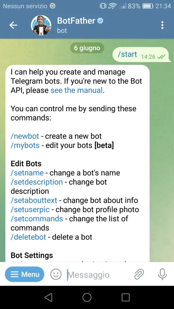
Now type the command /newbot to create your bot. Give it a name and username:
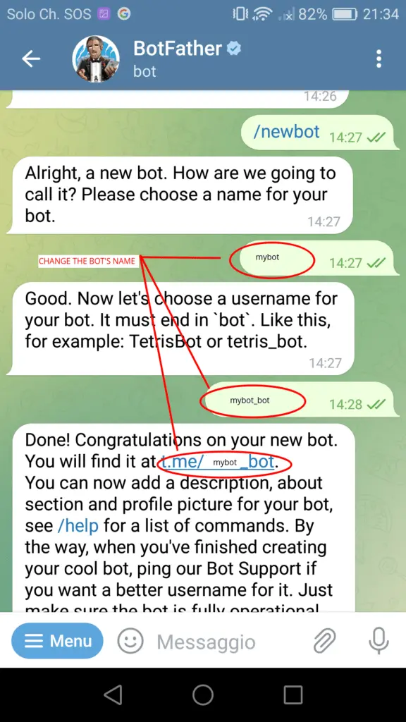
If your bot was created successfully, you will receive a message with a link to access the bot and the bot token.
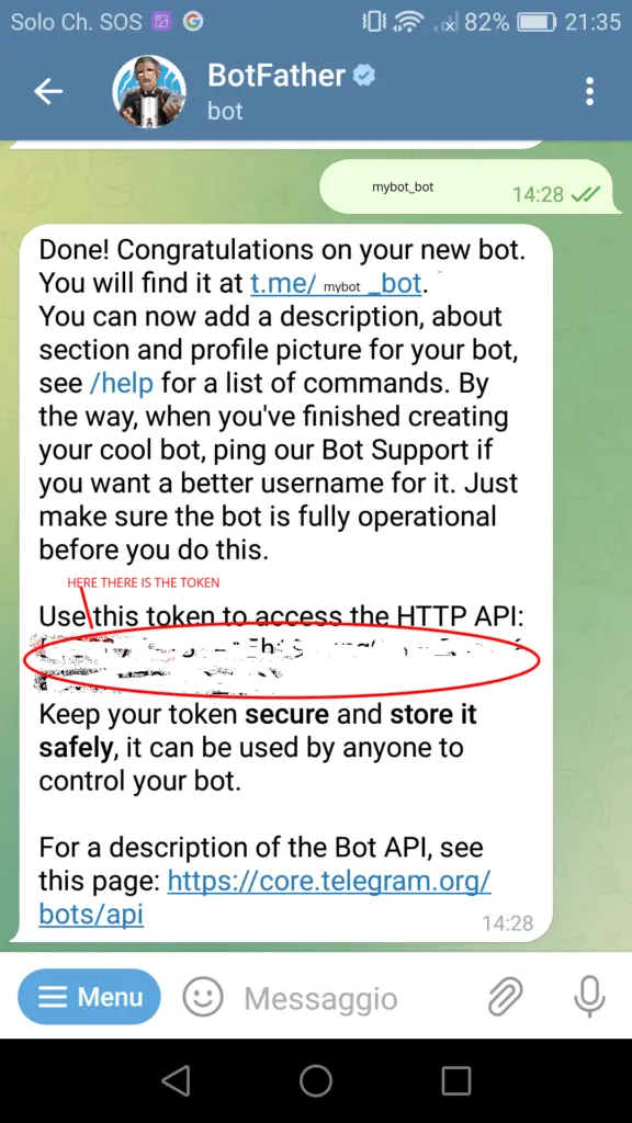
Save the bot token as you will need it later for the board to interact with the bot.
This is what the screen where the bot token is written looks like:
Anyone who knows your bot’s username can interact with it. To filter messages to ignore those that don’t come from your Telegram account, you need to use your Telegram User ID. Thus, when your Telegram bot receives a message, our Freenove will know if it comes from us (and therefore process it) or from someone else (and therefore ignore it). But…..how do we find this ID?
In your Telegram account, search for IDBot and start a conversation with that bot:
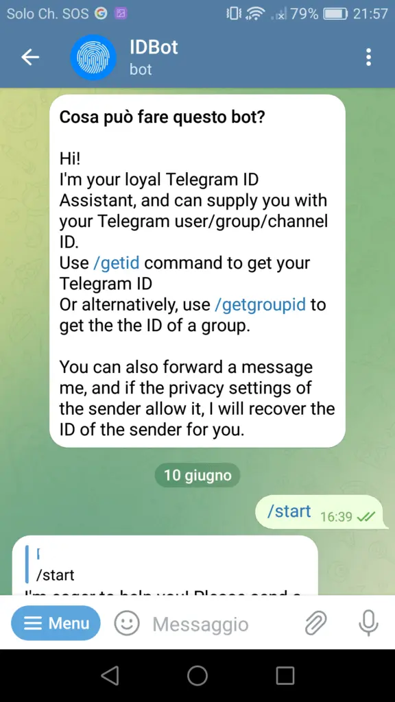
Then type the command /getid and it will reply with your ID:
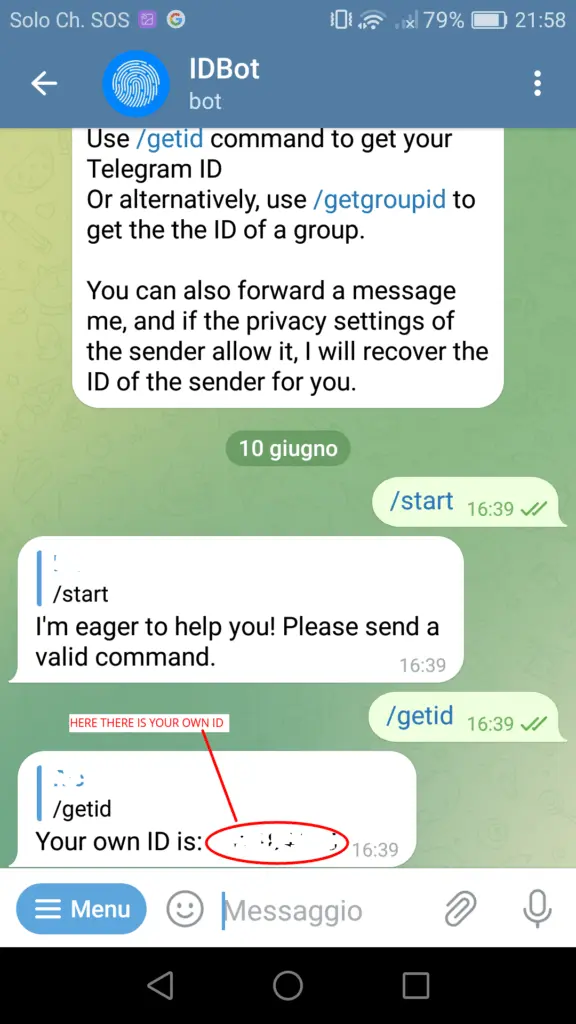
At this point we have created our bot and we have all the elements to interface it with our device: the username, the token and the userid.
The sketch
Let’s now analyze the code we uploaded to the board.
Initially we include the necessary libraries:
#include <Arduino.h>

#include "esp_camera.h"
#include <WiFiManager.h>
#include <WiFiClientSecure.h>

#include <UniversalTelegramBot.h>   // Universal Telegram Bot Library written by Brian Lough: https://github.com/witnessmenow/Universal-Arduino-Telegram-Bot
#include <ArduinoJson.h>


#include <EEPROM.h>                // EEPROM
We use them to manage the EEPROM, the camera, the WiFi connection and the connection to the Telegram bot. The ArduinoJson library is a dependency of the UniversalTelegramBot library.
// Initialize Telegram BOT
String BOTtoken = "XXXXXXXXXXXXXXXXXXXXXXXXXXXXXXXXXXXXXXXXXXXXXX";  // your Bot Token (Get from Botfather)

// Use @myidbot to find out the chat ID of an individual or a group
// Also note that you need to click "start" on a bot before it can
// message you
String CHAT_ID = "YYYYYYYYYYYY";
Here we need to enter the token and the Telegram User ID parameters that we got in the previous step when we created the Telegram bot.
// Checks for new messages every 1 second.
int botRequestDelay = 1000;
unsigned long lastTimeBotRan;

WiFiClientSecure client;
UniversalTelegramBot bot(BOTtoken, client);
In this piece we define the variables that manage the receipt of messages from the bot and we define the WiFi client and the Telegram bot.
#define CAMERA_MODEL_WROVER_KIT // Has PSRAM

#include "camera_pins.h"
Here the model of camera used is defined and the file describing the pins used by the camera is included.
int triggerPort = 33;             // GPIO33
int echoPort = 32;                // GPIO32
float distanceTrigger = 3.0;
int checkDistanceTime = 2000;      // milliseconds
Here the GPIOs used by the ultrasonic sensor are defined (triggerPort and echoPort), the distance within which the board must detect a movement (distanceTrigger) and then take the picture and the checkDistanceTime variable which defines how often the ultrasonic sensor must do a measure. It is recommended not to go below the set value (2 seconds) in order not to cause malfunctions (the camera takes some time to take a picture and send it to the bot).
Please note: the HC-SR04 ultrasonic sensor is not able to measure distances greater than 4 meters, therefore it is advisable to give the distanceTrigger variable a value no greater than 3.
bool sendPhoto = false;
String alarmStatusEE = "";
int alarmStatusEE_address = 2;
This part initializes the sendPhoto variable (which when set to true causes the photo to be taken) and initializes the alarmStatusEE variable which stores the alarm status (whether automatic or manual) and the EEPROM address where it will be saved for keep it in case of power failure.
The handleNewMessages function manages the messages exchanged with the bot. In particular:
if (text == "/help") {

    String welcome = "Welcome, " + from_name + ".\n";
    welcome += "Use the following commands to control your outputs:\n\n";
    welcome += "/photo takes a picture manually\n\n";
    welcome += "/aon to turn automatic mode ON\n\n";
    welcome += "/aoff to turn automatic mode OFF\n\n";
    welcome += "/aget gets the status of the alarm (automatic or manual mode)\n\n";

    bot.sendMessage(chat_id, welcome, "");
}
shows a welcome message with possible commands and their explanations when the /help command is issued.
else if (text == "/photo") {
         sendPhoto = true;
         bot.sendMessage(chat_id, "Sending a picture....");
    }
Here the /photo command is managed which sets the sendPhoto variable which when set to true causes the photo to be taken and sends a notification message.
else if (text == "/aon") {
          alarmStatusEE = "1";
          EEPROM.write(alarmStatusEE_address, alarmStatusEE[0]);
          EEPROM.commit();
          bot.sendMessage(chat_id, "Alarm set to ON (automatic mode).", "");
    }
Here the /aon command is managed which sets the device in automatic mode and saves this state in the EEPROM. In this mode it is always possible to take a photo manually by issuing the /photo command.
else if (text == "/aoff") {
          alarmStatusEE = "0";
          EEPROM.write(alarmStatusEE_address, alarmStatusEE[0]);
          EEPROM.commit();
          bot.sendMessage(chat_id, "Alarm set to OFF (manual mode).", "");
    }
Here the /aoff command is managed which sets the device in manual mode and saves this state in the EEPROM. In this mode, no photos are taken automatically but only manually (again with the /photo command).
else if (text == "/aget") {
      alarmStatusEE = char(EEPROM.read(alarmStatusEE_address));
      if (alarmStatusEE == "1") {
        bot.sendMessage(chat_id, "Alarm set to ON (automatic mode).", "");
      } else if (alarmStatusEE == "0"){
        bot.sendMessage(chat_id, "Alarm set to OFF (manual mode).", "");
      }
      else {
        bot.sendMessage(chat_id, "Alarm set to unknown state!!", "");
      }
    }
This part manages the /aget command which returns the device status (automatic or manual).
else {
       bot.sendMessage(chat_id, "Unrecognized message. Please retry...", "");
    }
Finally, the case in which the command is not recognized because it is different from those expected is managed.
The sendPhotoTelegram function takes a photo and sends it to the bot:
const char* myDomain = "api.telegram.org";
String getAll = "";
String getBody = "";
In this first part, the Telegram URL to which to send the photo and two service variables are defined.
camera_fb_t * fb = NULL;
  fb = esp_camera_fb_get();
  esp_camera_fb_return(fb); // dispose the buffered image
  fb = NULL; // reset to capture errors
  fb = esp_camera_fb_get(); // get fresh image

  if(!fb) {
    Serial.println("Camera capture failed");
    delay(1000);
    ESP.restart();
    return "Camera capture failed";
  }  else {
    Serial.println("Camera capture OK");
  }
Here the photo is taken and a possible malfunction of the camera is managed by restarting the board.
if (client.connect(myDomain, 443)) {
    Serial.println("Connection successful");

    String head = "--Techrm\r\nContent-Disposition: form-data; name=\"chat_id\"; \r\n\r\n" + CHAT_ID + "\r\n--Techrm\r\nContent-Disposition: form-data; name=\"photo\"; filename=\"esp32-cam.jpg\"\r\nContent-Type: image/jpeg\r\n\r\n";
    String tail = "\r\n--Techrm--\r\n";

    uint16_t imageLen = fb->len;
    uint16_t extraLen = head.length() + tail.length();
    uint16_t totalLen = imageLen + extraLen;

    client.println("POST /bot"+BOTtoken+"/sendPhoto HTTP/1.1");
    client.println("Host: " + String(myDomain));
    client.println("Content-Length: " + String(totalLen));
    client.println("Content-Type: multipart/form-data; boundary=Techrm");
    client.println();
    client.print(head);


    uint8_t *fbBuf = fb->buf;
    size_t fbLen = fb->len;
    Serial.println(fbLen);

    for (size_t n=0;n<fbLen;n=n+1024) {
      if (n+1024<fbLen) {
        client.write(fbBuf, 1024);
        fbBuf += 1024;
      }
      else if (fbLen%1024>0) {
        size_t remainder = fbLen%1024;
        client.write(fbBuf, remainder);
      }
    }

    client.print(tail);


    esp_camera_fb_return(fb);

    int waitTime = 10000;   // timeout 10 seconds
    long startTimer = millis();
    boolean state = false;

    while ((startTimer + waitTime) > millis()){
      Serial.print(".");
      delay(100);
      while (client.available()) {
        char c = client.read();
        if (state==true) getBody += String(c);
        if (c == '\n') {
          if (getAll.length()==0) state=true;
          getAll = "";
        }
        else if (c != '\r')
          getAll += String(c);
        startTimer = millis();
      }
      if (getBody.length()>0) break;
    }
    client.stop();
    Serial.println(getBody);
  }
  else {
    getBody="Connected to api.telegram.org failed.";
    Serial.println("Connected to api.telegram.org failed.");
  }
  return getBody;
This piece of code is what actually sends the photo to the Telegram bot.
The setup function deals, as usual, with the initialization of the peripherals:
pinMode( triggerPort, OUTPUT );     // sets the pin as OUTPUT for the ultrasonic sensor
pinMode( echoPort, INPUT );         // sets the pin as INPUT for the ultrasonic sensor
The triggerPort and echoPort pins that manage the ultrasonic sensor are set as OUTPUT and INPUT respectively.
WiFi.mode(WIFI_STA); // explicitly set mode, esp defaults to STA+AP
  // it is a good practice to make sure your code sets wifi mode how you want it.

  Serial.begin(115200);

  EEPROM.begin(512);  //Initializes EEPROM

  //WiFiManager, Local intialization. Once its business is done, there is no need to keep it around
  WiFiManager wm;
This part initializes the serial port, EEPROM and WiFi management.
bool res;
  // res = wm.autoConnect(); // auto generated AP name from chipid
  // res = wm.autoConnect("AutoConnectAP"); // anonymous ap
  res = wm.autoConnect("AutoConnectAP","password"); // password protected ap

  if(!res) {
      Serial.println("Failed to connect");
      // ESP.restart();
  }
  else {
      //if you get here you have connected to the WiFi
      Serial.println("Connected...yeey :)");
  }
This part manages the initial connection of the board as an Access Point.
client.setCACert(TELEGRAM_CERTIFICATE_ROOT); // Add root certificate for api.telegram.org

  config_init();   // configures the cam


  bot.sendMessage(CHAT_ID, "Hi! I'm online!", "");

  bot.sendMessage(CHAT_ID, "Ready to operate. Type /help to see the command list.", "");
Finally the certificate for Telegram is added, the camera is configured and the initial welcome messages are sent to the bot.
Now let’s look at the loop function.
if (sendPhoto) {
    Serial.println("Preparing photo");
    sendPhotoTelegram();
    sendPhoto = false;
 }
This first piece of code checks the state of the sendPhoto variable; if true then the photo is taken and the variable is set back to false.
if (millis() > lastTimeBotRan + botRequestDelay)  {
    int numNewMessages = bot.getUpdates(bot.last_message_received + 1);

    while(numNewMessages) {
      Serial.println("got response");
      handleNewMessages(numNewMessages);
      numNewMessages = bot.getUpdates(bot.last_message_received + 1);
    }
    lastTimeBotRan = millis();
  }
This part deals with managing the timing of receiving messages from the bot.
if(millis() - lastRefreshTime >= checkDistanceTime)
	{
		lastRefreshTime += checkDistanceTime;
    Serial.println(lastRefreshTime);

    digitalWrite(triggerPort, LOW);			// set to LOW trigger's output
    digitalWrite(triggerPort, HIGH);		// send a 10us pulse to the trigger
    delayMicroseconds(10);
    digitalWrite(triggerPort, LOW);

    long duration = pulseIn(echoPort, HIGH);

    long r = 3.4 * duration / 2;			// here we calculate the distance using duration

    float distance = r / 100.00;

    float distanceMeters = distance / 100;


    Serial.print("duration: ");
    Serial.print(duration);
    Serial.print(" , ");
    Serial.print("distance: ");


    if( (duration > 38000) or (duration == 0) ) Serial.println("out of reach");		// if duration in greather than 38ms, the obstacle is out of reach. If the duration equals 0 the sensor is in error
    else {
      Serial.print(distance); Serial.print("cm, ");
      Serial.print(distance/100); Serial.println("m");

      if((distanceMeters <= distanceTrigger) and (alarmStatusEE == "1"))
      {
        bot.sendMessage(CHAT_ID, "Intruder detected!", "");
        sendPhoto = true;
      }
    }
	}
This part takes care of making distance measurements every checkDistanceTime seconds and deciding whether to take the photo.
The photo will be taken only if the device is set to automatic (the alarmStatusEE variable is set to “1”) and the just measured distance of the moving object (distanceMeters) is less than the one set at the start of the sketch (distanceTrigger).
Finally, the config_init function configures the camera pins, initializes it and sets some characteristics of the image to be taken:
camera_config_t config;
config.ledc_channel = LEDC_CHANNEL_0;
config.ledc_timer = LEDC_TIMER_0;
config.pin_d0 = Y2_GPIO_NUM;
config.pin_d1 = Y3_GPIO_NUM;
config.pin_d2 = Y4_GPIO_NUM;
config.pin_d3 = Y5_GPIO_NUM;
config.pin_d4 = Y6_GPIO_NUM;
config.pin_d5 = Y7_GPIO_NUM;
config.pin_d6 = Y8_GPIO_NUM;
config.pin_d7 = Y9_GPIO_NUM;
config.pin_xclk = XCLK_GPIO_NUM;
config.pin_pclk = PCLK_GPIO_NUM;
config.pin_vsync = VSYNC_GPIO_NUM;
config.pin_href = HREF_GPIO_NUM;
config.pin_sscb_sda = SIOD_GPIO_NUM;
config.pin_sscb_scl = SIOC_GPIO_NUM;
config.pin_pwdn = PWDN_GPIO_NUM;
config.pin_reset = RESET_GPIO_NUM;
config.xclk_freq_hz = 20000000;
//config.frame_size = FRAMESIZE_QVGA;
config.pixel_format = PIXFORMAT_JPEG; // for streaming
//config.pixel_format = PIXFORMAT_RGB565; // for face detection/recognition
config.grab_mode = CAMERA_GRAB_WHEN_EMPTY;
config.fb_location = CAMERA_FB_IN_PSRAM;
//config.jpeg_quality = 12;
//config.fb_count = 1;

//init with high specs to pre-allocate larger buffers
if(psramFound()){
config.frame_size = FRAMESIZE_UXGA;
config.jpeg_quality = 10;  //0-63 lower number means higher quality
config.fb_count = 1;
} else {
config.frame_size = FRAMESIZE_SVGA;
config.jpeg_quality = 12;  //0-63 lower number means higher quality
config.fb_count = 1;
}

// camera init
esp_err_t err = esp_camera_init(&config);
if (err != ESP_OK) {
Serial.printf("Camera init failed with error 0x%x", err);
return;
} else {
Serial.println("Camera init OK");
}

sensor_t * s = esp_camera_sensor_get();
s->set_vflip(s, 0);        //1-Upside down, 0-No operation
s->set_hmirror(s, 0);      //1-Reverse left and right, 0-No operation
s->set_brightness(s, 1);   //up the blightness just a bit
s->set_saturation(s, -1);  //lower the saturation
s->set_framesize(s, FRAMESIZE_CIF);  // UXGA|SXGA|XGA|SVGA|VGA|CIF|QVGA|HQVGA|QQVGA
And here is a video demonstration of the video surveillance system working
In the video below you can see a small demonstration of how our simple video surveillance system works:
On the screen you can see on the left the shot of the scene made by the webcam of my laptop, on the right the screenshot of the Telegram bot created earlier (it is Telegram for desktop i.e. the computer version).
Initially the room is empty and the device is set to manual. I play the part of the intruder. I’m offstage and I’m holding the mobile phone with which I interact with the Telegram application installed on it and which is connected to the same bot. I give the /help command to bring up the instruction screen, then I give the /photo command to send me a screenshot of the empty room, finally I check the operating status (manual or automatic) with the /aget command which confirms that the operating mode is set to manual.
At some point I give the /aon command and the device goes into automatic mode. From now on, the motion detection function via the ultrasonic sensor is working. As I enter the room, the sensor detects my presence, the board starts taking pictures every 2 seconds (as long as I’m within range of the sensor) and sending them to me via Telegram. At 1:57 I deactivate the automatic mode with the /aoff command. From this moment on, the ultrasonic motion sensor is deactivated and you can only take pictures manually with the /photo command.
Final considerations
As you can see, the project is not particularly complex and its operation is also quite simple, not being able to be compared to a commercial device. But this, like all the projects presented in this blog, is an experiment and, as such, can be perfected and expanded with new and more complex features (the only limit is your imagination).
The ultrasonic sensor is not very precise as it sometimes detects movements even when there are none, giving rise to false positives (and therefore unrepresentative photos).
The ESP32, in order to send the photos, needs a stable and fast WiFi network. Otherwise the board risks blocking the sending of the image. This is one of the reasons why it is good that the interval between one measurement and another by the ultrasonic sensor is not less than 2 seconds.
Newsletter
If you want to be informed about the release of new articles, subscribe to the newsletter. Before subscribing to the newsletter read the page Privacy Policy (UE)
If you want to unsubscribe from the newsletter, click on the link that you will find in the newsletter email.
🔗 Follow us on our social channels so you don’t miss any updates!
📢 Join our Telegram channel to receive real-time updates.
🐦 Follow us on Twitter to always stay informed about our news.
Thank you for being part of our TechRM community! 🚀