Introduction
Nowadays we all have to deal with video surveillance systems: on the streets, in shops, at home (to control unwanted access by any bad guys or perhaps to secretly observe the behavior of our pets in our absence). Today’s technology helps us as it provides us with increasingly miniaturized and cheap boards, cameras and storage systems. Just think of the size (and cost) of the video cameras of a few decades ago!
Today we have boards available that are capable of managing a very small camera, connecting to the Internet via WiFi and sending us the images taken in real time, without needing our presence.
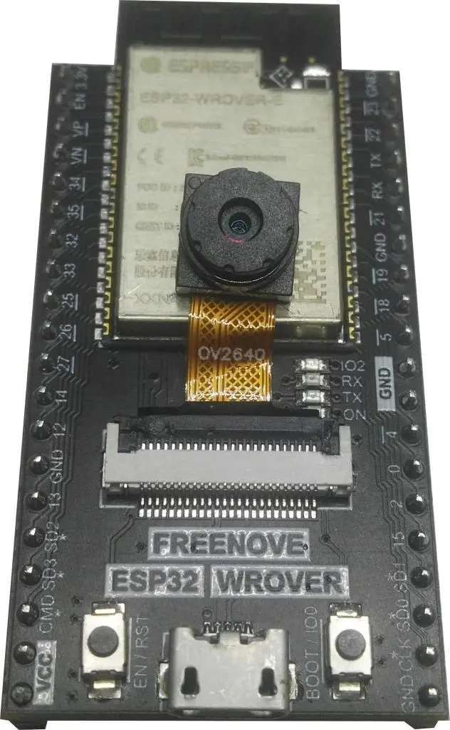
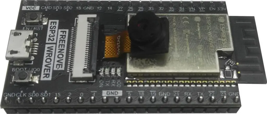
One of these boards is the Freenove based on ESP32-WROVER chip equipped with a tiny but effective camera:


As mentioned, the board is equipped with an OV2640 model camera capable of taking still and moving images.
What components do we need for our video surveillance ESP32 PlatformIO project?
We only need the Freenove ESP32-WROVER CAM Board with camera, which can be purchased on Amazon at this link.
How is our video surveillance system made?
The realization is very simple because, as mentioned above, the only hardware we need is the board complete with camera and the usual USB cable needed to connect it to the PC and program it.
Once the firmware has been loaded, it will be necessary to configure the board so that it connects to our WiFi network. Once the board is connected, it will give us its URL via the Serial Monitor. We just have to open that URL in our browser and see the images taken.
Let’s create the project for the sketch on PlatformIO
We have already seen in a previous article how to create a project using the excellent PlatformIO IDE. So let’s create our project following the indications of article How to create a project for NodeMCU ESP8266 with PlatformIO. Although it refers to the ESP8266 board, the procedure is similar.
Simply, in the platform choice menu we will have to choose the Espressif ESP-WROVER-KIT.
Let’s skip the part on how to add the libraries to the project as we will add the only one we need (WifiManager) in a different way.
The platformio.ini file, which you will find in the project downloadable from the link below, you will need to modify so that it contains the following lines (after the commented header):
[env:esp-wrover-kit]
platform = espressif32
board = esp-wrover-kit
framework = arduino
monitor_speed = 115200
upload_speed = 921600
board_build.partitions = huge_app.csv
build_flags = -DBOARD_HAS_PSRAM
lib_deps = https://github.com/tzapu/WiFiManager.git
With these settings we are defining the platform (esp-wrover-kit), the speed of the Serial Monitor (115200), the loading speed of the sketch (921600), the type of memory partition to use (huge_app.csv), the presence of a PSRAM (-DBOARD_HAS_PSRAM) and the WiFiManager library directly from its repository (https://github.com/tzapu/WiFiManager.git).
But since a video is more explanatory than a thousand words, here is the video on how to create the project:
While from the link below you can download the project:
Overwrite the main.cpp file with the one you just downloaded and copy the app_httpd.cpp file into the src folder and the camera_index.h and camera_pins.h files in the include folder.
Compile the project and upload it to the board. If there are no errors, the next step will be to connect the device to the WiFi network.
How to connect the board to the Internet
After uploading the sketch to the board, open the Serial Monitor to see the messages coming from the device.
First the board goes into Access Point mode and will give us an IP address which we will use shortly. This operation is used to connect the board to the Internet without having to enter the WiFi network parameters (SSID and password) in the code.

In this case the IP address is 192.168.4.1.
At this point the Freenove is in Access Point mode (with SSID AutoConnectAP) and we need to connect our computer to the AutoConnectAP network. If we go to the networks menu of our computer, we should also see the AutoConnectAP network in the list of wireless networks.

Connect your computer to the AutoConnectAP network. Then go to your browser and enter the IP previously provided by Freenove: 192.168.4.1
You will see a screen like this:

Click the ConfigureWiFi button. It will show you the available networks:

Choose the SSID of your network:

Enter your network password and click the save button:


The Freenove module keeps the login parameters memorized even if you turn it off, it will remember them when you restart and it will automatically reconnect without having to repeat this procedure. Only if you reset it by uncommenting this line:
// wm.resetSettings();
will lose the connection parameters.
Please note: the device can memorize only one network. If you later connect it to another network, it will forget the previous network settings.
Once connected, the board provides us with its IP and the URL that we must open in the browser:

The next video shows how it works in more detail:
As you can see from the last part of the video, the camera has many controls:

They range from the choice of resolution to the classic controls of brightness, contrast, color, saturation and so on.
The sketch
As usual the sketch starts with the inclusion of the necessary libraries:
#include <Arduino.h>

#include "esp_camera.h"
#include <WiFiManager.h>
Then follows the definition of the type of camera:
#define CAMERA_MODEL_WROVER_KIT // Has PSRAM
The camera_pins.h file located in the include folder is then included:
#include "camera_pins.h"

camera_config_t config;

void startCameraServer();
void config_init();
the config object is defined, for configuring the camera, and the two functions startCameraServer and config_init are declared.
The setup function contains the part relating to the activation of the serial port, the WiFi management:
WiFi.mode(WIFI_STA); // explicitly set mode, esp defaults to STA+AP
// it is a good practice to make sure your code sets wifi mode how you want it.

Serial.begin(115200);

//WiFiManager, Local intialization. Once its business is done, there is no need to keep it around
WiFiManager wm;

// reset settings - wipe stored credentials for testing
// these are stored by the esp library
// wm.resetSettings();

// Automatically connect using saved credentials,
// if connection fails, it starts an access point with the specified name ( "AutoConnectAP"),
// if empty will auto generate SSID, if password is blank it will be anonymous AP (wm.autoConnect())
// then goes into a blocking loop awaiting configuration and will return success result

bool res;
// res = wm.autoConnect(); // auto generated AP name from chipid
// res = wm.autoConnect("AutoConnectAP"); // anonymous ap
res = wm.autoConnect("AutoConnectAP","password"); // password protected ap

if(!res) {
    Serial.println("Failed to connect");
    // ESP.restart();
}
else {
    //if you get here you have connected to the WiFi
    Serial.println("Connected...yeey :)");
}
and the settings of the camera with the printing of the url to open:
config_init();

// camera init
esp_err_t err = esp_camera_init(&config);
if (err != ESP_OK) {
    Serial.printf("Camera init failed with error 0x%x", err);
    return;
} else {
    Serial.println("Camera init OK");
}

sensor_t * s = esp_camera_sensor_get();
s->set_vflip(s, 0);        //1-Upside down, 0-No operation
s->set_hmirror(s, 0);      //1-Reverse left and right, 0-No operation
s->set_brightness(s, 1);   //up the blightness just a bit
s->set_saturation(s, -1);  //lower the saturation

startCameraServer();

Serial.print("Camera Ready! Use 'http://");
Serial.print(WiFi.localIP());
Serial.println("' to connect");
We don’t need the loop function so it’s empty.
At the end of the sketch we find the config_init function:
config.ledc_channel = LEDC_CHANNEL_0;
config.ledc_timer = LEDC_TIMER_0;
config.pin_d0 = Y2_GPIO_NUM;
config.pin_d1 = Y3_GPIO_NUM;
config.pin_d2 = Y4_GPIO_NUM;
config.pin_d3 = Y5_GPIO_NUM;
config.pin_d4 = Y6_GPIO_NUM;
config.pin_d5 = Y7_GPIO_NUM;
config.pin_d6 = Y8_GPIO_NUM;
config.pin_d7 = Y9_GPIO_NUM;
config.pin_xclk = XCLK_GPIO_NUM;
config.pin_pclk = PCLK_GPIO_NUM;
config.pin_vsync = VSYNC_GPIO_NUM;
config.pin_href = HREF_GPIO_NUM;
config.pin_sscb_sda = SIOD_GPIO_NUM;
config.pin_sscb_scl = SIOC_GPIO_NUM;
config.pin_pwdn = PWDN_GPIO_NUM;
config.pin_reset = RESET_GPIO_NUM;
config.xclk_freq_hz = 20000000;
config.frame_size = FRAMESIZE_QVGA;
config.pixel_format = PIXFORMAT_JPEG; // for streaming
//config.pixel_format = PIXFORMAT_RGB565; // for face detection/recognition
config.grab_mode = CAMERA_GRAB_WHEN_EMPTY;
config.fb_location = CAMERA_FB_IN_PSRAM;
config.jpeg_quality = 12;
config.fb_count = 1;
which does nothing but configure the pins of the camera connected to the ESP32 module and other parameters relating to the type of image produced.
Final considerations
The camera used is theoretically capable (but these functions have not been tested by us) of also performing face detection/recognition functions.
As we have seen, the browser connects to the camera via the URL http://ip where ip is the IP of the device. This IP is related to the internal network (for example the network of the router in our house) so it is not visible from the outside, i.e. if our PC is connected to an external network (such as when, for example, we are away from home).
To be able to do this we should first have a static device IP (so that it never changes). In general the board is always assigned the same IP (unless it’s already assigned to some other device) so this shouldn’t be a big deal. However, to make this internal IP visible to the outside, it is necessary to use the so-called port forwarding which allows you to give access from the outside to a device on the local network that has a private address.
Newsletter
If you want to be informed about the release of new articles, subscribe to the newsletter. Before subscribing to the newsletter read the page Privacy Policy (UE)
If you want to unsubscribe from the newsletter, click on the link that you will find in the newsletter email.
🔗 Follow us on our social channels so you don’t miss any updates!
📢 Join our Telegram channel to receive real-time updates.
🐦 Follow us on Twitter to always stay informed about our news.
Thank you for being part of our TechRM community! 🚀