What is an operational amplifier?
The operational amplifier (also called opamp) is a solid-state analog electronic component capable, as its name suggests, of amplifying an electrical signal. It is defined as operational because it is able to perform some mathematical operations in a totally analogical way on electrical signals. The generally possible operations are addition, subtraction, derivation and integration, logarithm and so on.
It is also a fundamental part of active low-pass, high-pass, band-pass, notch filters.
It has two inputs, one inverting (indicated with the – sign) and one non-inverting (indicated with the + sign), and one output. It is generally fed with a dual voltage (usually indicated with the signs V+ and V–).
In case the signal enters through the non-inverting input, the output signal is with the same phase as the input signal. If, on the other hand, the signal enters the inverting input, the output signal will be in phase opposition (that is, 180 degrees out of phase) with respect to the input signal.
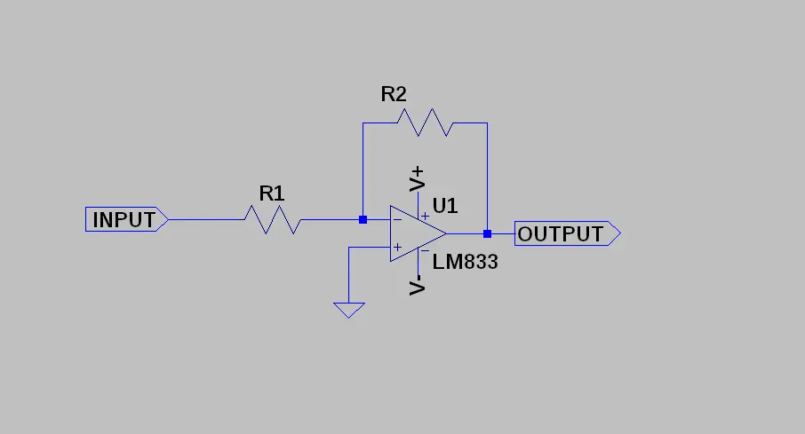
An inverting amplifier is, therefore, an operational amplifier whose non-inverting input is connected to ground while the inverting one is connected to the input source VINPUT.

This circuit takes the signal at the INPUT terminal and reproposes it in OUTPUT amplified (ie multiplied by a value called gain which we will indicate with the symbol G).
So, in the formula, we have that:
VOUTPUT = G * VINPUTWe have said that this amplifier inverts the phase of the output signal with respect to the phase of the input signal (the two signals are 180 degrees out of phase). This means that the value of G is negative. For example, if the input signal were amplified 10 times, we would have G = -10 [V/V] and therefore:
VOUTPUT = -10 * VINPUTIf, for example, the signal VINPUT = 1V we would have VOUTPUT = -10 V while with VINPUT = -1 V we would have VOUTPUT = 10 V.
In practice, the output signal is given by the input signal magnified by 10 times and reversed.
NOTE: the gain, being the ratio between two voltages
G = VOUTPUT / VINPUTis expressed by a pure number. However, we can express it, alternatively, with the notation [V/V] (which is always a pure number).
How do you set the gain of the inverting amplifier?
The gain is easily determined starting from the values of the two resistances R1 and R2. In particular we have that the gain, in absolute value, is given by:
|G| = R2 / R1Therefore, if we had R1 = 1 kΩ and R2 = 10 KΩ, we would have |G| = 10.
Considering the phase shift of 180 degrees we have that
G = -R2 / R1With the values of the previous example we have that G = -10 [V/V].
Said in other words:
VOUTPUT = -(R2 / R1) * VINPUTthat is:
VOUTPUT = -10 * VINPUTThe gain can also be expressed in dB (decibel) according to the relationship:
GdB = 20 * log(|G|) = 20 * log(|-R2 / R1|) = 20 * log (R2 / R1)For example, if R1 and R2 were 1 kΩ and 10 kΩ respectively, we would have G = -10 [V/V] and GdB = 20 dB. If R1 and R2 were 2 kΩ and 15 kΩ respectively, we would have G = -7.5 [V/V] and GdB = 17.5 dB.
If you want to simulate the circuit, you can use the well-known LTspice software that we too have used abundantly with our amplifier.
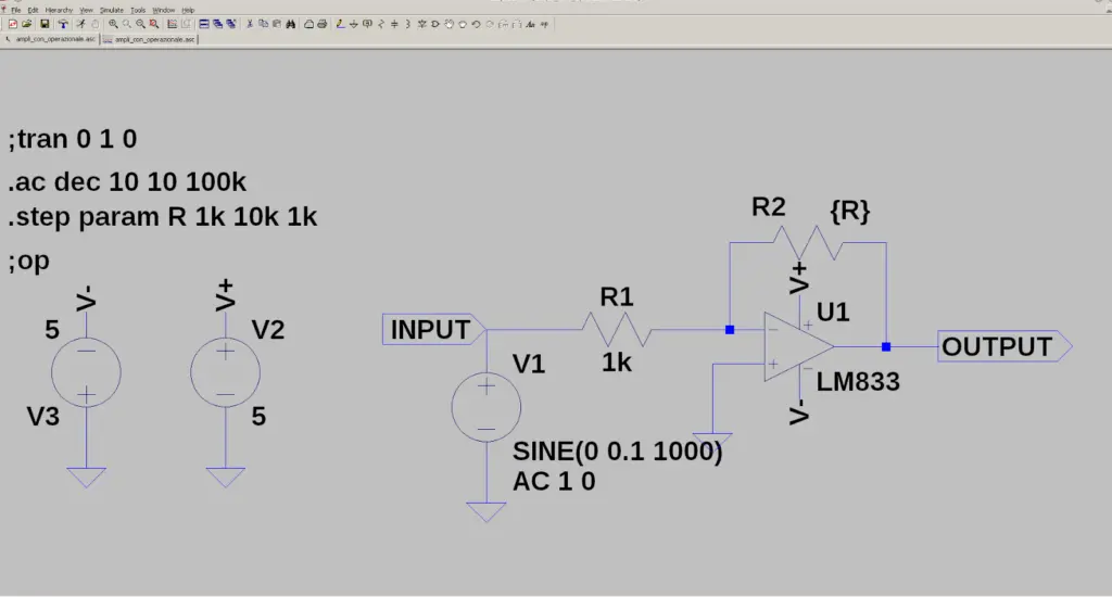
First of all we draw the schematic and then we simulate it (in the time domain and in the frequency domain):

We want to determine the gain of the amplifier as a function of the value of R2.
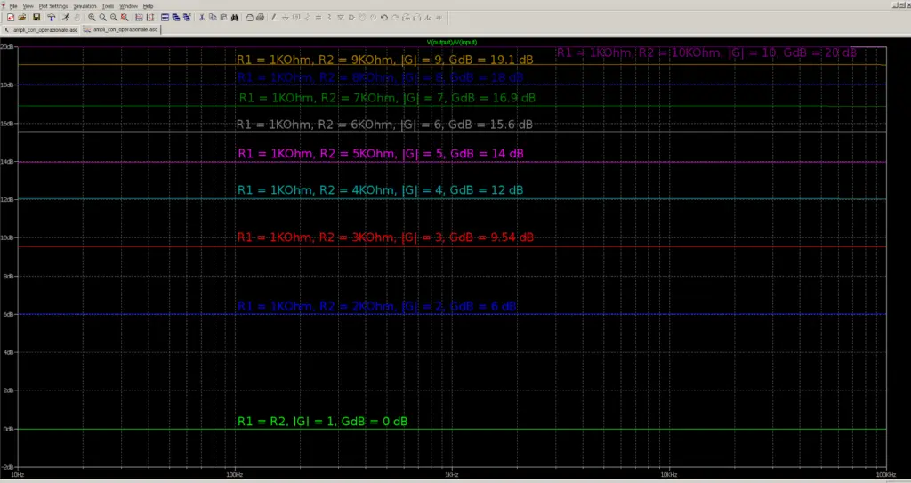
In our scheme there is a SPICE directive (.step param R 1k 10k 1k) which ensures that the simulation is carried out for various values of R2. The resistance R2 will therefore assume the initial value of 1 kΩ and will be increased by 1 kΩ for each step until it reaches the maximum value of 10 kΩ. If we carry out the simulation in the frequency domain we can observe that the GdB gain varies according to the value of R2:
- R1 = 1KΩ, R2 = 1KΩ, |G| = 1, GdB = 0 dB, Vin-peak = 0.1 V, Vout-peak = 0.1 V
- R1 = 1KΩ, R2 = 2KΩ, |G| = 2, GdB = 6 dB, Vin-peak = 0.1 V, Vout-peak = 0.2 V
- R1 = 1KΩ, R2 = 3KΩ, |G| = 3, GdB = 9.54 dB, Vin-peak = 0.1 V, Vout-peak = 0.3 V
- R1 = 1KΩ, R2 = 4KΩ, |G| = 4, GdB = 12 dB, Vin-peak = 0.1 V, Vout-peak = 0.4 V
- R1 = 1KΩ, R2 = 5KΩ, |G| = 5, GdB = 14 dB, Vin-peak = 0.1 V, Vout-peak = 0.5 V
- R1 = 1KΩ, R2 = 6KΩ, |G| = 6, GdB = 15.6 dB, Vin-peak = 0.1 V, Vout-peak = 0.6 V
- R1 = 1KΩ, R2 = 7KΩ, |G| = 7, GdB = 16.9 dB, Vin-peak = 0.1 V, Vout-peak = 0.7 V
- R1 = 1KΩ, R2 = 8KΩ, |G| = 8, GdB = 18 dB, Vin-peak = 0.1 V, Vout-peak = 0.8 V
- R1 = 1KΩ, R2 = 9KΩ, |G| = 9, GdB = 19.1 dB, Vin-peak = 0.1 V, Vout-peak = 0.9 V
- R1 = 1KΩ, R2 = 10KΩ, |G| = 10, GdB = 20 dB, Vin-peak = 0.1 V, Vout-peak = 1 V
By doing the simulation we see how the gain varies at each step:

In the image below you can see the variations of VOUTPUT as the gain G varies (in turn a function of R2):

Let’s now try to build a simple prototype amplifier with fixed gain. If we take R1 and R2 equal to 1 kΩ and Rd equal to 4.7 kΩ the gain will be equal to G = – (R2 + Rd)/R1 = -5.7 [V/V] (15.12 dB):

What components do we need for our inverting op amp Arduino project with a digital potentiometer?
Prototype creation
Let’s now try to build the circuit on a breadboard following the Fritzing diagram below:

The two 47kΩ resistors divide the supply voltage (9V) to create a virtual ground. So the junction of the two resistors is the ground of the circuit while the two dual supplies will be V+ = 4.5V and V– = -4.5V with respect to the virtual ground.
Here’s what our prototype looks like:

The image below shows the input signal in light blue (with a peak value of 0.42V) and the output signal in yellow (with a peak value of 2.32V). The absolute value of the gain is therefore equal to 2.32V/0.42V = 5.52 [V/V]. From the image it can also be seen that the two signals are 180 degrees out of phase (that is, they are in phase opposition) precisely because it is an inverting amplifier (which inverts the phase of the output signal with respect to that of the input signal):

Now let’s replace the resistor Rd with our digital potentiometer.
For more information on how to control a digital potentiometer via Arduino, please take a look at our article How to control a digital potentiometer usinhomg Arduino UNO
Now let’s connect our circuit as shown in the figure below:

In this case we have two separate power supplies: the dual one for the operational amplifier that we have seen before and the 5V one coming from Arduino to power the digital potentiometer.
The virtual ground of the operational amplifier and the ground of the Arduino coincide.
The sketch
You can download the code from the link below:
For the first test we set the value of Rd to 4.7 kΩ so the loop function of the sketch should be like this:
void loop() {
    int i = 128; // R = 4700 Ω
    spi_out(CS_signal, cmd_byte2, i);
}
In this case the resistance is always constantly set at 4.7 kΩ so the gain does not vary.
Let’s load the sketch on the Arduino, put a sinusoidal signal (amplitude 0.4 – 0.5 V, f = 1 khz) at the input of the amplifier and measure the output.
In our test circuit we have this situation: input signal peak value 0.4V with f = 1khz, output signal peak value 2.24V. The gain is therefore equal to 5.6V/V.

Now let’s try to dynamically change the gain of the amplifier, alternating between two values of Rd (4.7 kΩ and 9 kΩ) so the loop function of the sketch should look like this:
void loop() {
    int i = 128; // R = 4700 Ω
    spi_out(CS_signal, cmd_byte2, i);
    Serial.print("value i = ");
    Serial.print(i);
    Serial.println(" R = 4700 Ω");
    delay(5000);

    i = 0; // R = 9000 Ω
    spi_out(CS_signal, cmd_byte2, i);
    Serial.print("value i = ");
    Serial.print(i);
    Serial.println(" R = 9000 Ω");
    delay(5000);
}
In the video below you can see the result of the test:
The gain varies between 5.4 (corresponding to Rd = 4.7 kΩ) and 9 (corresponding to Rd = 9 kΩ).
In the video below we can see how the value of Rd varies measured with a digital multimeter (without the operational amplifier):
Newsletter
If you want to be informed about the release of new articles, subscribe to the newsletter. Before subscribing to the newsletter read the page Privacy Policy (UE)
If you want to unsubscribe from the newsletter, click on the link that you will find in the newsletter email.
🔗 Follow us on our social channels so you don’t miss any updates!
📢 Join our Telegram channel to receive real-time updates.
🐦 Follow us on Twitter to always stay informed about our news.
Thank you for being part of our TechRM community! 🚀