Introduction
If you’re looking to control an SG90 servo motor via Bluetooth, the ESP32 is an ideal solution. The ESP32 is a very powerful microcontroller that offers built-in Bluetooth capabilities, making it perfect for remote control projects. In this article, I’ll walk you step-by-step through the process of setting up the ESP32 to control an SG90 servo via Bluetooth. You’ll learn how to use Kai Morich’s Serial Bluetooth Terminal application to send commands to your SG90 servo motor, and you’ll see how to build a complete project that will allow you to control the motion of your servo motor remotely. With this guide, you will be able to create a custom remote control system that will allow you to control your devices from anywhere.
What is a servo motor?
A servo motor is a type of electric motor that uses a control signal to place a shaft or arm in a specific position and keep that position stable. It consists of a motor, a control circuit, and a feedback device, such as a potentiometer or encoder, which measures the position of the shaft or arm and feeds it back to the control circuit. Servo motors are commonly used in applications that require precise position control, such as robotics, factory automation, model aircraft, and mechanical device control. The SG90 servomotor that we will use here has 3 connection wires: two for the 5V power supply and the third for its control. Being small and not very powerful, it is suitable for acting on small loads.
What components do we need for our SG90 servo motor Bluetooth control project with ESP32?
The list of components is not particularly long:
- a breadboard to connect the ESP32 NodeMCU to the other components
- some DuPont wires (male – male, male – female, female – female)
- an SG90 servo motor
- and, of course, an ESP32 NodeMCU !
Project realization
The wiring scheme
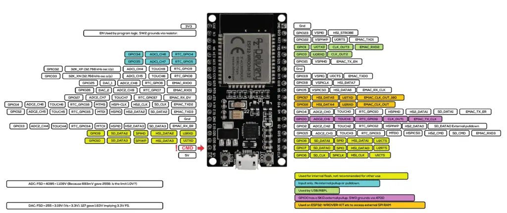
Before realizing the actual circuit let’s look at the pinout of the board:

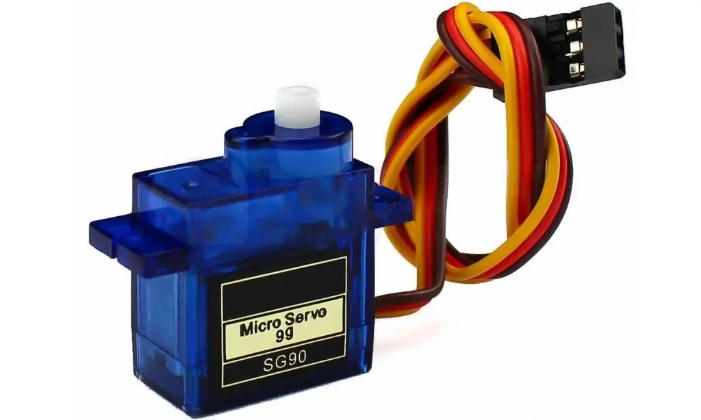
While the servomotor looks like this:

Note the unusual colors used for the connecting wires. In particular we have:
- the brown wire will be connected to the ground
- the red wire will be connected to the 5V pin of the ESP32
- the orange wire is the control one and we will connect it to GPIO 19 of the ESP32
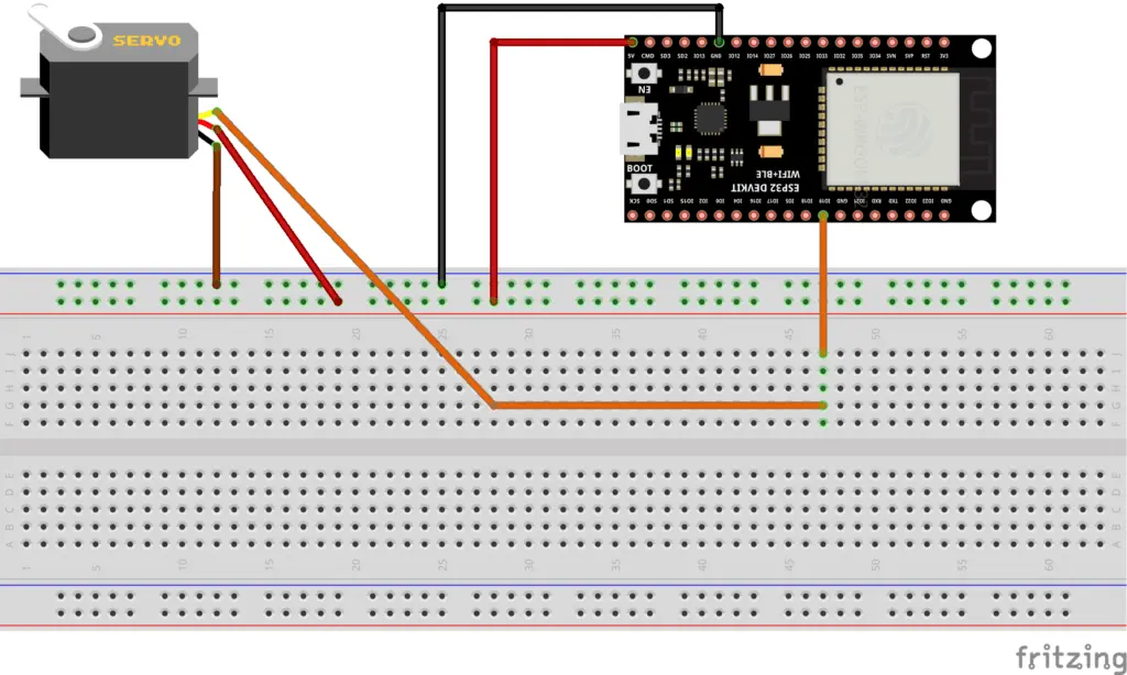
Here, in the following image, the wiring diagram created using Fritzing:

As you can see the wiring is quite simple. Actually you could even do without the breadboard, unless you want to add a few more components. The only thing to pay attention to is the fact that the color of the wires is particular (with the conventions mentioned above).
The sketch
Let’s create the PlatformIO project
We have already seen the procedure for creating a PlatformIO project in article How to create a project for NodeMCU ESP8266 with PlatformIO.
Although it refers to the ESP8266 board, the procedure is similar.
Simply, when choosing the platform, you will have to choose the AZ-Delivery ESP-32 Dev Kit C V4.
Do not install the libraries indicated in that article because we don’t need them in this project. But you must, following the procedure indicated in the article, install the ServoESP32 library by Jaroslav Paral:

Then install the BluetoothSerial by Seeed library as shown in the following image:

Now edit the platformio.ini file to add these two lines:
monitor_speed = 115200
upload_speed = 921600
so that the file looks like this:
[env:az-delivery-devkit-v4]
platform = espressif32
board = az-delivery-devkit-v4
monitor_speed = 115200
upload_speed = 921600
framework = arduino
lib_deps =
	roboticsbrno/ServoESP32@^1.0.3
	mbed-seeed/[email protected]+sha.f56002898ee8
Of course you can download the project from the following link:
Replace the main.cpp file of the project you created with the one present in the zip file.
Now let’s see how the sketch works.
The sketch begins with the inclusion of the necessary libraries for managing the servo and Bluetooth:
#include <Arduino.h>

#include "BluetoothSerial.h"

#include <Servo.h>
The myServo object, the GPIO to which it is connected and the servoPosition variable which stores the angular value of the servo position are then defined:
Servo myServo;  // create servo object to control a servo

#define SERVO_GPIO 19

int servoPosition = 0;    // variable to store the servo position
The SerialBT object is then defined which will manage the Bluetooth and the BTData variable in which the data will transit through the serial port:
BluetoothSerial SerialBT;
byte BTData;
At this point we meet the setup function which initially sets the speed of the serial port:
Serial.begin(115200);
delay(2000);
Then initialize the myServo object by connecting it to GPIO 19:
myServo.attach(SERVO_GPIO); // attaches the servo on pin 19 to the servo object
Bluetooth is then activated:
SerialBT.begin();
Serial.println("Bluetooth Started! Ready to pair...");
If you want to assign a specific name to the ESP32 Bluetooth device, you need to specify it as an argument to the SerialBT.begin() function. For example, if you want to name it myESP32BT, enter SerialBT.begin(“myESP32BT”).
If you leave the command without a parameter, such as SerialBT.begin(), the default name ESP32 will be applied.
We now meet the loop function.
The first part reads the character sent by the application on the mobile phone (which we will see later) to the ESP32 and prints it on the Serial Monitor:
if(SerialBT.available())
{
  BTData = SerialBT.read();
  Serial.write(BTData);
}
The decoding of the commands follows:
if(BTData == '0')
{
  servoPosition = 20;
}

if(BTData == '+')
{
  servoPosition++;
}

if(BTData == '-')
{
  servoPosition--;
}

if(BTData == 'A')
{
  servoPosition -= 10;
}

if(BTData == 'B')
{
  servoPosition += 10;
}

if(BTData == 'C')
{
  servoPosition = 180;
}
Now let’s see how these commands work:
- if the Bluetooth receives 0 it sets the angle to 20 degrees
- if the Bluetooth receives + it increases the angle by 1 degree
- if the Bluetooth receives – it decreases the angle by 1 degree
- if the Bluetooth receives A it decreases the angle by 10 degrees
- if the Bluetooth receives B it increases the angle by 10 degrees
- if the Bluetooth receives C it sets the angle to 180 degrees
Why did we impose a minimum limit of 20 degrees instead of setting 0 degrees? Because we have noticed that all of the SG90 servos at our disposal start to vibrate uncontrollably when the angle is set to 20 degrees or lower.
After decoding the commands, they are executed:
if((servoPosition >= 20) && (servoPosition <= 180))
{
  myServo.write(servoPosition);
  delay(100);
}
The if block checks that the angle value is within the appropriate range. If so, the angle is written to the servo (this is the real command to the servomotor) and they wait 100ms to give it time to execute the movement
The Serial Bluetooth Terminal application
To send the Bluetooth commands to the ESP32 I chose to use Kai Morich’s Serial Bluetooth Terminal application. You can download it from the Play Store.
Now turn on Bluetooth in your smartphone and search for Bluetooth devices. You should see a list of Paired Devices and Available Devices. Go to Available Devices.
Select ESP32 if you left the SerialBT.begin() line without a parameter in the sketch, otherwise choose the device with the name you put as a parameter in that line. Your mobile phone will ask you if you want to pair it with ESP32 (or with the name you set for it). At this point give OK. No need for passwords.
Open the Serial Bluetooth Terminal application and click on the point indicated in the following image:

Select the Devices item as shown in the figure below:

Another menu will open from which you will have to select your device (for example ESP32):

Now click on the point indicated in the following image to connect the application to the selected device:

Hopefully the connection should establish:

Now you need to record the commands to be sent to the device with macros in the application. Hold down the M1 key. The menu for editing it will open:

Instead of M1, put the + character in the Name field and always fill the Value field with the + character, then save by pressing at the indicated point:

Repeating the exact same procedure, perform the following associations:
- on M2 put the character – in the Name and Value fields
- on M3 put the label -10 in the Name field and the character A in the Value field
- on M4 put the label +10 in the Name field and the character B in the Value field
- on M5 put the label 0 in the Name field and the character 0 in the Value field
- on M6 put the label 180 in the Name field and the character C in the Value field
At the end you should have a screen like this:

Pressing the + or – keys will increase or decrease the position of the servomotor shaft by one degree. Pressing the +10 or -10 keys will increase or decrease the servo shaft position by 10 degrees. Pressing the 0 key will bring the servomotor shaft to the initial angle (as already explained, corresponding to 20 degrees), pressing the 180 key will bring it to the final angle (corresponding to 180 degrees).
Video demonstrating how the SG90 servo motor works
Here is a short video showing the control of the SG90 servo motor via Bluetooth:
Newsletter
If you want to be informed about the release of new articles, subscribe to the newsletter. Before subscribing to the newsletter read the page Privacy Policy (UE)
If you want to unsubscribe from the newsletter, click on the link that you will find in the newsletter email.
🔗 Follow us on our social channels so you don’t miss any updates!
📢 Join our Telegram channel to receive real-time updates.
🐦 Follow us on Twitter to always stay informed about our news.
Thank you for being part of our TechRM community! 🚀