Introduction
In this article we will create a simple RFID access control.
In the increasingly interconnected and security-oriented era, access control becomes crucial to ensuring protected and efficiently managed environments. In this context, the use of RFID (Radio-Frequency Identification) technology and devices such as the ESP8266 takes on a central role. In our article we will explore an innovative project that uses an ESP8266, an RFID module and a relay to create an intelligent and customizable access control system. We will discover how, thanks to a dictionary that associates RFID codes with access permissions, it is possible to manage the activation of a relay in a safe and efficient way. A versatile implementation that finds applications in scenarios such as controlling doors, gates or other restricted access areas.
As usual we will use the excellent PlatformIO IDE to write the code.
What is RFID technology
Radio-Frequency Identification (RFID) is an automatic identification system that uses electromagnetic fields to transfer data between a reader and an RFID tag. This technology is based on contactless communication and allows the storage and retrieval of information from objects, animals or people equipped with RFID tags. Here are some key points regarding the operation and use of RFID:
- Principle of operation:
- An RFID system is composed of a reader (or interrogator) and one or more RFID tags.
- The tag contains a chip that stores a unique code or other information.
- When the tag is in the electromagnetic field of the reader, it receives energy and transmits the stored data to the reader.
- Operating frequencies:
- RFIDs operate at different frequencies, mainly divided into low frequency (LF), high frequency (HF), ultra high frequency (UHF), and very high frequency (VHF).
- Different frequencies affect the reading distance and ability to penetrate through materials.
- Types of RFID tags:
- Tags can be active (with battery) or passive (without battery).
- Passive tags are powered by the reader field and have a shorter read distance than active tags.
- Common applications:
- Access control: RFID badge for automatic opening or security authentication.
- Logistics and traceability: monitoring goods in transit through warehouses and distribution chains.
- Contactless payments: contactless payment systems such as contactless cards.
- Security and privacy:
- RFID can present security and privacy challenges, with the potential for data to be intercepted and cloned.
- Various encryption techniques have been developed to protect the information exchanged between readers and tags.
- Implementation with ESP8266:
- The ESP8266 can be used as an RFID reader, interfacing with a compatible RFID module.
- The information read from the RFID tag can be used to trigger specific actions or access resources.
The use of RFID offers an effective and cost-effective solution for multiple applications, enabling the automation of processes and improving operational efficiency.
Description of operation
Our RFID access control system based on ESP8266 and RFID module offers intelligent and personalized access management. Using a dictionary that associates individual RFID codes with specific permissions, the device is able to discriminate between authorized and unauthorized users. When a user presents his RFID badge to the reader, the system consults the dictionary and, based on the associated permission, can activate or not activate a relay.
- Authorized access: in case of a positive match between the RFID code and the permission in the dictionary, the relay is activated for a pre-established period, allowing the opening of a door or gate. This functionality finds ideal application in contexts such as offices, warehouses or reserved areas.
- Access denied: if the RFID code is not present in the dictionary or if the associated permission is limited, the relay remains inactive, ensuring that the unauthorized user cannot access the protected area. This level of control is essential for security in sensitive environments.
- Flexible customization: the dictionary allows for flexible permission management, allowing the administrator to add, modify or revoke access to specific users as needed.
PLEASE NOTE: in this project an opto-isolated double relay module is used but we will only use one of the two relays. So you can also choose a single opto-isolated relay module or use the double one, perhaps activating one of the two relays by a badge and the other relay by another badge or the key ring.
What is a dictionary
- Dictionary definition:
- In programming, a dictionary is a data structure that allows you to store key-value pairs.
- Each dictionary element consists of a unique key associated with a value.
- Structure and access:
- Dictionaries are structured to allow quick access to values via keys.
- Values are accessed by specifying the associated key, allowing efficient retrieval of information.
- Keys and Values:
- The keys in a dictionary are usually strings, numbers, or other immutable data types.
- Values can be of any type, including numbers, strings, lists, or even other dictionaries.
- Utilities and applications:
- Dictionaries are widely used to manage structured data and associate information flexibly.
- They are especially useful when data must be accessed via unique identifiers rather than fixed locations.
- Common operations:
- Adding new key-value pairs:
myDictionary[key] = value. - Removing a pair:
delete.myDictionary[key] - Retrieving the value associated with a key:
value=myDictionary[key]
- Adding new key-value pairs:
- Iteration:
- You can iterate over all keys, values, or key-value pairs in the dictionary.
- This allows you to perform operations on all elements of the dictionary efficiently.
- It is possible to extract the list of all the keys or all the values present in the dictionary.
- Implementation in the ESP8266:
- In programming contexts for the ESP8266, dictionaries are often used to manage configurations, dynamic key-value associations, or map relevant information.
- Efficiency and complexity:
- The efficiency of accessing data via keys makes dictionaries an ideal choice for situations where fast retrieval of information is necessary.
- The time complexity for search, insert, and delete operations is often very low compared to other data structures.
Using dictionaries adds a level of flexibility and organization to programs, allowing for efficient and dynamic management of information.
The RFID kit used in this project
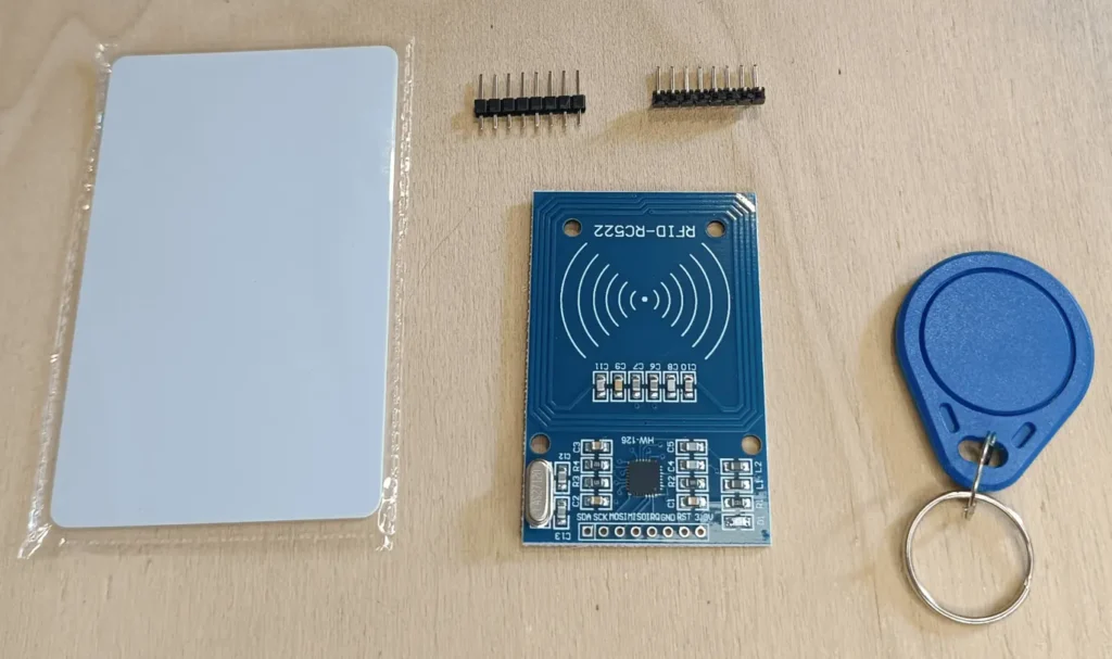
The kit, distributed by the AZ-DELIVERY company, consists of an RFID reader, a badge, a key ring (always RFID), two types of connectors to be soldered onto the reader (one with straight contacts and one with right-angled contacts) . If you are not familiar with the world of soldering irons and want to try soldering the connector yourself, I recommend you take a look at the article Yet another tutorial on how to solder.
Both the badge and the key ring contain a code that can be read by the RFID reader. In my case the badge has hexadecimal code 7351E99 while the key ring has hexadecimal code A35CDB.
For the purposes of the project I set the dictionary within the sketch so that the A35CDB code can trigger the relay while the 7351E99 code prevents this operation.
The RFID reading module interfaces with the ESP8266 via SPI communication which we will discuss in the next paragraph.
In the next photo you can see the complete kit:

SPI interface
The RFID reader module uses SPI interface, which is a 4-wire serial communication protocol commonly used in embedded projects. These four wires are:
- MISO (Master In Slave Out): this is the pin through which the module receives data from the master device, which is usually the Arduino or another microcontroller.
- MOSI (Master Out Slave In): this is the pin through which the module sends data to the master device.
- SCK (Serial Clock): this is the clock pin that synchronizes data transmission between the module and the master device.
- CS (Chip Select): this pin is used to select the RFID module and initialize data sending/receiving operations.
What components do we need for the ESP8266 RFID access control system?
The list of components is not particularly long:
- a breadboard to connect the ESP8266 NodeMCU to other components
- some DuPont wires (male – male, male – female, female – female)
- an RFID kit like the one shown in the previous paragraph
- a module with single/double opto-isolated relay
- and, of course, an ESP8266 NodeMCU!
As regards the choice of the relay module, the considerations at the end of the “Description of operation” paragraph apply.
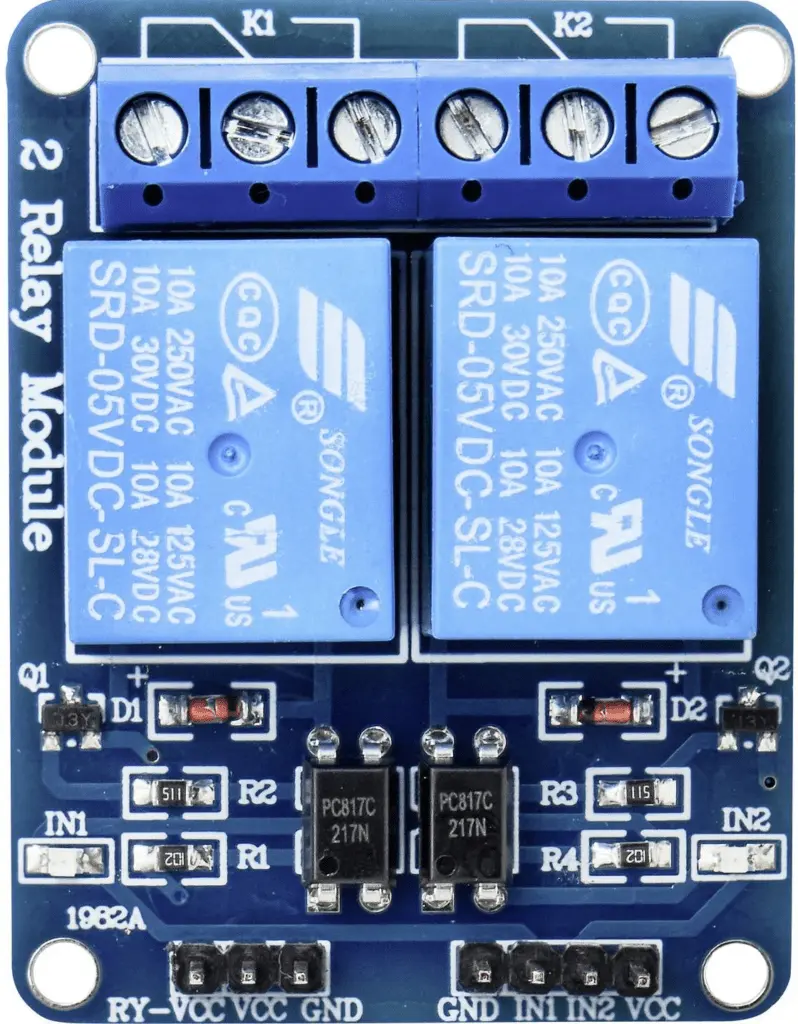
The double relay module
- Power supply:
- It accepts a wide range of supply voltages, usually between 5V and 12V.
- The power connector is designed to be easily connected to an external power source, such as a battery or power supply.
- Relay:
- Two relays on board, each with its own electrical contacts: common (COM), normal open (NO) and normal closed (NC).
- The relay contacts are designed to handle power loads. However, the exact specifications depend on the specific model of the relay module.
- Control Inputs:
- Two control inputs (IN1 and IN2) that can be connected to digital pins of an Arduino-type development board.
- Activating one of these inputs with a high (or low, as appropriate) logic signal will activate the corresponding relay.
- LED indicators:
- Built-in LED indicators for each relay that indicate activation status (often with colors such as red for activated and off for deactivated).
- Arduino compatibility:
- Designed to be easily integrated with development platforms such as Arduino, making relay control a simple and accessible operation.
- Pilotable Loads:
- Capable of driving a variety of electrical loads such as light bulbs, motors, solenoid valves, and other devices requiring on/off control.
- The exact load specifications depend on the relay model, but they can often handle loads with alternating voltages up to 250V and currents up to 10A.
These relay modules are widely used in home automation, electronic automation and remote control projects, providing a safe and controlled interface for power devices.

Project implementation
The wiring diagram of RFID access control with ESP8266
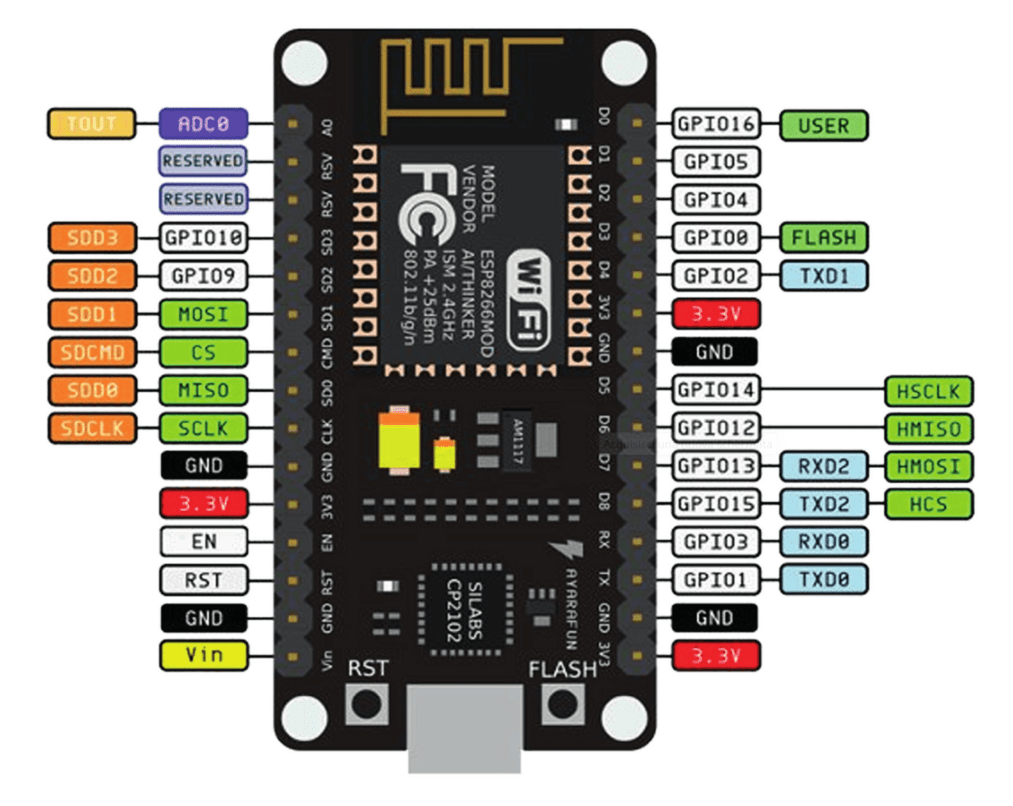
Before creating the actual circuit let’s take a look at the pinout of the board:

Below we see the pinout of the RFID module:

The IRQ pin will not be used.
Let’s now see the electrical diagram of the project, created as usual with Fritzing:

As can be seen from the diagram, only one relay will be used, the one connected to the IN1 input.
As you can see the scheme is not particularly complex. Rather you have to pay attention to the power supplies since they are separated between the sensor power section and the relay module power section. As you can see, the power for the sensor is taken from the NodeMCU’s 3.3V output (pin 3V3). It is necessary to power it with 3.3V so that its output is also 3.3V as the digital pins of the NodeMCU do not accept voltages higher than 3.3V.
Instead, the power supply to the relay module is taken from the Vin pin of the NodeMCU which supplies the 5V necessary to drive the relay coils.
PAY ATTENTION: in the ESP8266 NodeMCU the maximum voltage tolerated by the digital inputs is equal to 3.3V. Any higher voltage would damage it irreparably!!
Currently the double relay module is not present in Fritzing but, if you want to use it in your projects, you can download it from here.
Let’s analyze the connection of the relay module in more detail.
The two Vin and GND pins of the ESP8266 NodeMCU are used to power the dual relay module, connecting the Vin pin (NodeMCU side) to the VCC pin (dual relay module side) and the two GND pins (ground).
Another connection is used to control the relay module via the orange wire that connects the digital output D1 of the NodeMCU to the IN1 input of the relay module.
You will notice that on the relay module there is a jumper (drawn in blue on the left connector) that connects the JD-VCC and VCC terminals. This jumper is used to power the relay module through the VCC and GND terminals on the right connector. Without this jumper, we would be forced to power the module with an external power supply.
The sketch
Let’s create the PlatformIO project
We have already seen the procedure for creating a PlatformIO project in the article How to create a project for NodeMCU ESP8266 with PlatformIO. You can follow the guide but do not install any of the indicated libraries.
Now edit the platformio.ini file so it looks like this:
[env:nodemcu]
platform = espressif8266
board = nodemcu
framework = arduino
monitor_speed = 115200
upload_speed = 921600
lib_deps =
	miguelbalboa/MFRC522@^1.4.11
	arkhipenko/Dictionary@^3.5.0
In this way we are directly inserting the libraries for managing the RFID sensor and for creating and managing the access dictionary.
Obviously you can download the project from the following link:
PLEASE NOTE: the sketch was created by deriving it from one of the examples provided by Miguel Balboa’s RFID library.
Replace the main.cpp file of the project you created with the one present in the zip file.
Now let’s see how the sketch works.
Initially the necessary libraries are included:
#include <SPI.h>
#include <MFRC522.h>
#include <Dictionary.h>
The GPIOs for the reset and chip select of the RFID sensor are then defined:
constexpr uint8_t RST_PIN = D0;     // Configurable, see typical pin layout above
constexpr uint8_t SS_PIN = D8;     // Configurable, see typical pin layout above
The mfrc522 object which will manage the RFID sensor and the uuidCode variable which will store the uuid code of the badge or key ring are then defined:
MFRC522 mfrc522(SS_PIN, RST_PIN);   // Create MFRC522 instance
String uuidCode = "";
Then the dictUsers dictionary is instantiated (specifying that there will only be two key-value pairs) and the GPIO that will be used to control the relay is defined:
Dictionary &dictUsers = *(new Dictionary(2));
const int relayPin = D1;
At the beginning of the setup function the dictionary is populated with the necessary information:
  dictUsers("A35CDB", "y");
  dictUsers("7351E99", "n");
As already mentioned, both the badge and the key ring contain a code that can be read by the RFID reader. In my case the badge has hexadecimal code 7351E99 while the key ring has hexadecimal code A35CDB.
In the dictionary I associated the value “y” to the key “A35CDB” and the value “n” to the key “7351E99”. We will see as the code continues that a value of “y” corresponds to access permitted (i.e. the relay will trip) while a value of “n” corresponds to access denied (the relay will not trip). Simply put, the user with code “A35CDB” will be able to open the door while the user with code “7351E99” will not be able to open it.
Following the setup function, the serial port, the SPI bus, the RFID sensor are initialized and then a message is printed on the Serial Monitor:
  Serial.begin(115200);                                           // Initialize serial communications with the PC
  SPI.begin();                                                  // Init SPI bus
  mfrc522.PCD_Init();                                              // Init MFRC522 card
  Serial.println(F("Read personal data on a MIFARE PICC:"));    //shows in serial that it is ready to read
Finally, the relay control pin is defined as OUTPUT and placed at HIGH level (in this relay model, it is activated if the level is LOW):
pinMode(relayPin, OUTPUT);
digitalWrite(relayPin, HIGH);
We then find the loop function which initially checks whether a badge has been brought near the sensor and, if so, reads its contents and prints the “Card detected” message:
// Look for new cards
if ( ! mfrc522.PICC_IsNewCardPresent()) {
return;
}

// Select one of the cards
if ( ! mfrc522.PICC_ReadCardSerial()) {
return;
}

Serial.println("\n**Card Detected:**");
Following is a part that inserts the detected code into the uuidCode variable, makes the characters uppercase and prints it on the Serial Monitor:
Serial.print("Card UID:  ");
for (byte i = 0; i < mfrc522.uid.size; i++) {
uuidCode = uuidCode + String(mfrc522.uid.uidByte[i], HEX);
}
uuidCode.toUpperCase();
Serial.println(uuidCode);
Let’s get to the part that decides who can open the door or not:
if(dictUsers[uuidCode] == "y") {
    Serial.println("access granted");
    Serial.println("opening the door");
    digitalWrite(relayPin, LOW);
    delay(5000);
    digitalWrite(relayPin, HIGH);
   Serial.println("closing the door");
} else {
   Serial.println("access denied");
}
We have an if block that checks the value returned by the dictionary corresponding to the code contained in the uuidCode variable. If the returned value is y then access is enabled, then the relevant messages are printed, the relay is activated by placing the control output at LOW, we wait 5 seconds after which the relay is deactivated by placing the control output at HIGH.
If the value returned by the dictionary is n, no action is performed other than printing the access denied message.
The loop ends by initializing the uuidCode variable and printing an end-of-read message:
uuidCode = "";
Serial.println(F("\n**End Reading**\n"));
Observations
Obviously the use of an access dictionary placed directly in the code makes its update not very immediate. Each time you have to modify the dictionary (for example if you add new users or change the access privileges of a given user), compile the sketch and upload it to the ESP8266.
A possible solution would be to write and update a Json document stored on an SD card and write the functions for its update and real-time reading of access privileges for each user.
Video of RFID access control operation
The following video shows how the device works:
Newsletter
If you want to be informed about the release of new articles, subscribe to the newsletter. Before subscribing to the newsletter read the page Privacy Policy (UE)
If you want to unsubscribe from the newsletter, click on the link that you will find in the newsletter email.
🔗 Follow us on our social channels so you don’t miss any updates!
📢 Join our Telegram channel to receive real-time updates.
🐦 Follow us on Twitter to always stay informed about our news.
Thank you for being part of our TechRM community! 🚀