Introduction
The control of the brightness of the LEDs (for example by means of potentiometers) is a fundamental element in the design of electronic systems and in the field of the Internet of Things (IoT). Thanks to PWM (Pulse Width Modulation) technology, it is possible to regulate the brightness of an LED in a precise and controlled way. In this article, we will explore how to use ESP32, a powerful IoT development board, together with the PlatformIO development environment, to control the brightness of two independent LEDs based on the reading of two independent potentiometers.
We will use PlatformIO as the development environment, which offers a simple and professional interface to develop projects based on microcontrollers such as the ESP32. We’ll take advantage of ESP32’s advanced features, including PWM signal support, to create a LED brightness control system that responds to potentiometer changes.
Through clear and detailed steps, we will learn how to connect potentiometers to the ESP32, acquire the values of the potentiometers using the analog inputs of the ESP32 and use the PWM signal to adjust the brightness of the LEDs according to the values read. We will also see how to properly configure PlatformIO for project development and how to write the necessary code to implement brightness control.
Whether you are new to the world of electronics or an experienced IoT developer, this article will guide you step-by-step through the process of creating an LED system dimmer control system, giving you a solid knowledge base to explore further projects and applications in the field of electronics and IoT.
So get ready to immerse yourself in the world of electronics and exploit the potential of ESP32 and PlatformIO to create a versatile and customizable control system for LED brightness.
What components do we need?
The list of components is not particularly long:
- a breadboard to connect the ESP32 NodeMCU to the other components
- some DuPont wires (male – male, male – female, female – female)
- two 22kΩ potentiometers (actually the value is not critical, they could also be 10kΩ) preferably with linear variation
- two 100Ω resistors
- two red LEDs
- and, of course, an ESP32 NodeMCU !
What are potentiometers and how do they work?
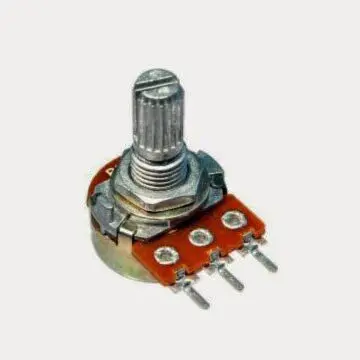
A potentiometer, also known as a variable resistor, is an electromechanical component that allows you to adjust the electrical resistance within a circuit. It consists of a cylindrical or rectangular body with an adjustment shaft and three terminals: one central and two extremes. The potentiometer is equipped with a slider, mechanically integral with the shaft, which moves along a resistive track inside the body. The position of the cursor determines the electrical resistance between the central terminal and one of the extreme terminals.
The operation of the potentiometer is based on the principle of variable resistance. As the cursor is moved along the resistive track, the length of the path through which the signal must pass changes, thus altering the overall resistance. This affects the amount of current that can flow between the slider and either side terminal. When the cursor is close to one of the extreme terminals, the resistance between the cursor and the other terminal is maximum, while the resistance between the cursor and the closest lateral terminal is minimum (practically zero).
A potentiometer can be used for a variety of purposes, such as adjusting the volume of an audio amplifier, the brightness of a display, or the speed of an electric motor. Its versatility derives from the possibility of continuously controlling the resistance value within a circuit, offering a wide range of regulation.
There are several types of potentiometers, including linear and logarithmic potentiometers. In linear potentiometers, the resistance between the slider and one of the terminals varies linearly with respect to the rotation of the shaft. In logarithmic potentiometers the variation takes place in a logarithmic manner. The choice of potentiometer type depends on the specific application and circuit requirements.
The potentiometer is typically used as a voltage divider.

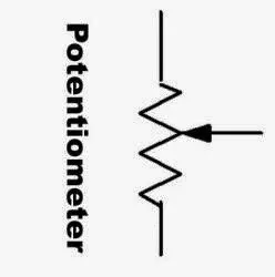
Its electrical symbol is that of a classic resistor but with the intermediate contact controlled by the knob:

There are also fully electronic potentiometers on the market. If you want to learn more about how they work and their possible use, you can consult the articles How to control a digital potentiometer using Arduino UNO and How to control an inverting operational amplifier using Arduino UNO and a digital potentiometer.
How does a voltage divider work?
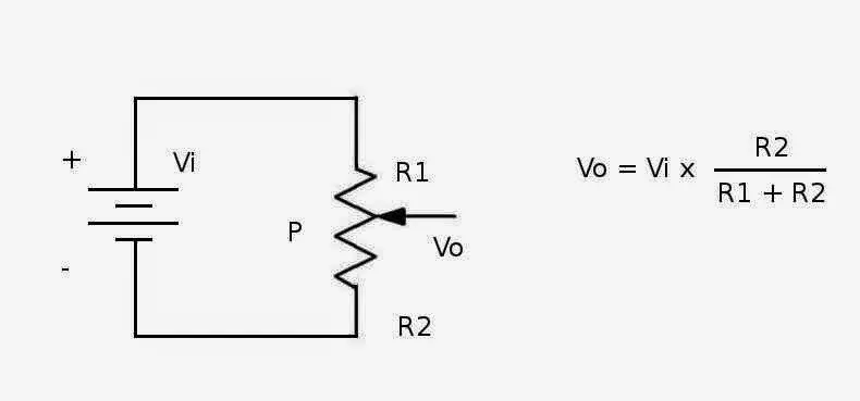
A voltage divider is a simple circuit where the output voltage is a fraction of the input voltage. You can use two fixed resistors or a potentiometer.
Let’s see the scheme and the formula:

The potentiometer is indicated with the letter P while R1 and R2 are the two sections of the total resistance which vary according to the position of the cursor (which is controlled by the knob).
As you can see, the output voltage Vo is a fraction of the input voltage Vi. Vo varies between two extremes:
- Vo = 0 when R2 = 0 (the knob is fully turned towards the terminal connected to the negative pole of the battery)
- Vo = Vi when R1 = 0 (the knob is fully turned towards the terminal connected to the positive pole of the battery)
In a digital system, such as the one based on ESP32 of this article, the voltage value Vo is acquired and made numerical by a special analog-digital converter, also indicated with the acronym ADC. In our case, having two independent potentiometers, we will use two analog inputs of the ESP32 (with the relative ADCs). The next paragraph will talk about the ADC in more detail.
What is an analog-to-digital converter (ADC)?
An analog-to-digital converter (ADC) is an electronic component that converts a continuous analog signal into a discrete digital signal. This process is essential when you want to measure and acquire data from sensors or other analog sources within a digital system. The ADC takes an analog signal, which represents a continuous physical quantity such as temperature, voltage or pressure, and converts it into a digital format that can be processed by a microcontroller or computer.
The operation of an ADC is based on two main phases: sampling and quantization. In the sampling process, the analog signal is measured at regular time intervals. The signal is sampled at discrete points, capturing a voltage value representative of the signal at that given instant of time. These samples are approximate representations of the original analog signal.
Later, in the quantization step, each sample is converted into a digital value. This process is done by assigning a numerical value to the analog sample based on a certain number of bits available for digital representation. The numerical value corresponds to a certain voltage level or intensity of the analog signal. For example, an 8-bit ADC can represent the signal with 256 discrete voltage levels (ranging from 0 to 255).
The accuracy of an ADC depends on its resolution, which is determined by the number of bits used for digital representation. An ADC with higher resolution can discriminate between smaller voltage levels, giving a more precise measurement of the analog signal. The difference between the true value of the analog signal at that instant and the discrete value that is attributed to it is called quantization error.
There are several variants of ADC, including ramping ADC, approximate succession ADC, and integrating ADC. Each of these has specific characteristics and performance that make them suitable for different applications.
In conclusion, an analog-to-digital converter (ADC) is an electronic component that converts a continuous analog signal into a discrete digital signal. Through the process of sampling and quantization, the ADC measures the analog signal at regular time intervals and converts it into a digital representation. This conversion allows analog data to be captured and processed in a digital system, enabling a wide range of applications in electronics, telecommunications and sensor control.
Project realization
The wiring diagram
Before realizing the actual circuit let’s look at the pinout of the board:

We will use GPIOs 5 and 18 to connect the LEDs and GPIOs 34 and 35 to connect the sliders of the two potentiometers. The brightness of each LED can be adjusted by rotating the cursor of the potentiometer associated with it. To obtain this result, it will be driven by the ESP32 via a PWM signal whose duty cycle varies as the value contained in a specific variable varies, a value that goes from 0 (LED OFF) to 255 (LED completely ON) passing through the intermediate values.
At this point you can proceed with the creation of the circuit by following the connection diagram below. Unfortunately, the ESP32 NodeMCU is too large to fit on the breadboard, which is why it will be connected with flying leads to the rest of the circuit.
The LEDs are connected to the ESP32 via 100Ω resistors to limit the current flowing through them and avoid burning them (and burning the digital outputs to which they are connected).
The LED has two terminals (called anode and cathode) and, like all diodes, it is a component that has its own polarity: it passes the current when it is forward polarized (i.e. the voltage at the anode is greater than that at the cathode) and it blocks current when it is reverse polarized (i.e. the anode voltage is lower than the cathode voltage). The voltage between the anode and cathode, which we will indicate with Vd, varies according to the color of the light emitted. In particular we have that:
- Vd = 1.8 V for red LEDs
- Vd = 1.9 V for yellow LEDs
- Vd = 2 V for green LEDs
- Vd = 2 V for orange LEDs
- Vd = 3 V for blu LEDs
- Vd = 3 V for white LEDs
Below is the wiring diagram created with Fritzing:

As you can see, the potentiometers power is taken from the 3.3V output of the NodeMCU (pin 3V3). It is necessary to feed them with 3.3V so that their maximum output is also 3.3V as the digital pins of the NodeMCU do not accept voltages higher than 3.3V
PAY ATTENTION: in the ESP32 NodeMCU the maximum voltage tolerated by the digital inputs is equal to 3.3V. Any higher voltage would damage it irreparably!!
How do we identify the anode and cathode of the LED? We do this by looking at its terminals. The longest corresponds to the anode. Also, the LED body has a flattening at one point on the edge indicating that the nearby terminal is the cathode.
So if an LED doesn’t light up it’s possible that it’s wired upside down. In this case, to make it work, simply reverse the connections.
How do you calculate the resistance to connect to the LED?
Please note: this paragraph deals with the calculation of the limiting resistance in a theoretical way and requires a minimum knowledge of the basics of Electrotechnics. Therefore it is not essential for understanding the rest of the project and can be skipped by the reader not interested in such theoretical aspects.
As we have already said, the resistor between the generic GPIO and the LED serves to limit the current flowing through the LED. But how can we calculate its resistance value? Ohm’s Law comes to our aid which says that the potential difference across a resistor (i.e. the voltage measured at the ends of the resistor) is proportional to the current I flowing through it and the constant of proportionality is precisely the resistance value of the resistor R:
V2 - V1 = RIPlease note: for the sake of precision it must be pointed out that while the resistor is the physical component (the actual object), the resistance is its value. So it is improper (even if it happens frequently) to call the resistor with the term resistance.
We can see Ohm’s Law on a simple circuit consisting of a voltage source (the circle on the left) and a resistor:

The voltage (or potential difference) V2 – V1 impressed by the voltage source on the resistor is equal to the product of R by I.
Now let’s see a slightly more complex scheme where the usual voltage generator, the resistor and a red LED are present:

In our case the Vg represents the voltage present at the digital output of the ESP32 when it is HIGH and is therefore equal to 3.3V.
Vd is the voltage across the diode (between anode and cathode) when it is forward biased (ie when it is carrying current). Having chosen a red LED, we know from the previous table that Vd = 1.8V.
We need to determine the R-value of the resistor. We still have one unknown: the value of the current I which must flow in the circuit when the pin is in the HIGH state.
Please note: when the digital pin is in the LOW state its voltage (ie Vg) is zero, it follows that also the current I in the circuit is zero.
LEDs generally cannot withstand currents greater than 20mA, so we impose a maximum current of 15mA to be on the safe side.
By Kirchhoff’s voltage law we have that:
Vg - Vr - Vd = 0From which we derive that:
Vr = Vg - Vd Passing to the real values, we have that:
Vr = 3.3V - 1.8VIt follows that:
Vr = 1.5VBut, by Ohm’s Law, we have that:
Vr = RIfrom which:
R = Vr / ISubstituting the real values:
R = 1.5V / 0.015AThe result is a value of R equal to 100Ω.
The sketch
Let’s create the PlatformIO project
We have already seen the procedure for creating a PlatformIO project in the How to create a project for NodeMCU ESP8266 with PlatformIO article.
Although it refers to the ESP8266 board, the procedure is similar.
Simply, when choosing the platform, you will have to choose the AZ-Delivery ESP-32 Dev Kit C V4.
Do not install the libraries indicated in that article because we don’t need them in this project.
Now edit the platformio.ini file to add these two lines:
monitor_speed = 115200
upload_speed = 921600
so that the file looks like this:
[env:az-delivery-devkit-v4]
platform = espressif32
board = az-delivery-devkit-v4
monitor_speed = 115200
upload_speed = 921600
framework = arduino
Of course you can download the project from the following link:
Replace the main.cpp file of the project you created with the one present in the zip file.
Now let’s see how the sketch works.
Initially the necessary libraries are included:
// Include the necessary libraries
#include <Arduino.h>
Then the GPIOs for the connection of the LEDs and potentiometers are defined:
// Define the pins for the LEDs
const int ledPin1 = 5;   // Pin for the first LED
const int ledPin2 = 18;  // Pin for the second LED

// Define the pins for the potentiometers
const int potPin1 = 34;  // Pin for the first potentiometer
const int potPin2 = 35;  // Pin for the second potentiometer
In the setup function, the serial port is first initialized:
 // Start the serial communication
 Serial.begin(115200);
 delay(2000);
and then the outputs to drive the two LEDs are defined:
 // Set the LED pins as outputs
 pinMode(ledPin1, OUTPUT);
 pinMode(ledPin2, OUTPUT);
Now let’s look at the loop function.
Initially the voltage values coming from the potentiometers are acquired, digitized and placed in the two variables potValue1 and potValue2:
 // Read values from the potentiometers
 int potValue1 = analogRead(potPin1);
 int potValue2 = analogRead(potPin2);
Subsequently, the values acquired and stored in the potValue1 and potValue2 variables are translated so as to be in the range 0 – 255 (which are the values allowed to drive the PWM signal) and stored in the brightness1 and brightness2 variables:
 // Map the values read from the potentiometers to the 0-255 range for PWM brightness
int brightness1 = map(potValue1, 0, 4095, 0, 255);
int brightness2 = map(potValue2, 0, 4095, 0, 255);
At this point the PWM outputs that drive the LEDs are set, with the duty cycles respectively given by brightness1 and brightness2:
 // Set the brightness of the LEDs using PWM signals
 analogWrite(ledPin1, brightness1);
 analogWrite(ledPin2, brightness2);
Subsequently the values acquired by the two potentiometers are printed on the Serial Monitor and a delay of 100ms is imposed in order to give time to the ESP32 to do all the operations.
 // Print the values read from the potentiometers to the serial port
 Serial.print("Potentiometer 1: ");
 Serial.print(potValue1);
 Serial.print(" - LED 1 Brightness: ");
 Serial.println(brightness1);

 Serial.print("Potentiometer 2: ");
 Serial.print(potValue2);
 Serial.print(" - LED 2 Brightness: ");
 Serial.println(brightness2);

 // Update the brightness every 100 milliseconds
 delay(100);
Once the sketch has been loaded, all you have to do is rotate the shafts of the two potentiometers to see how the brightness of the two LEDs varies accordingly.
The video of the operation of the project
In the following video you will notice how by turning each potentiometer you will be able to vary the brightness of the corresponding LED. You will also be able to see the variation of both PWM signals on the oscilloscope screen featured in the video. A low duty cycle corresponds to low brightness (or even LED off for zero duty cycle) while a high duty cycle corresponds to a higher brightness (with LED on at maximum for 100% duty cycle).
Newsletter
If you want to be informed about the release of new articles, subscribe to the newsletter. Before subscribing to the newsletter read the page Privacy Policy (UE)
If you want to unsubscribe from the newsletter, click on the link that you will find in the newsletter email.